Archive for the ‘Powder coating’ Category

Title frame

I continue to struggle keeping up with the blog posts. The work in the garage has not slowed down however writing about it has. Work and family life is busy and something had to give. I was, however, able to find some time to put together a post outlining what has been going on lately.

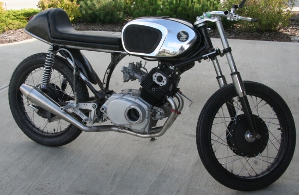
The work on the CB160 Cafe Racer continues to take place. My goal is to have it completed by spring and therefore progress needs to continually take place. I think I will be in good shape to make my deadline however there is always more work involved then one may expect. No time to start slacking.

My plan from the beginning was to perform as much of the fabrication work as possible while the bike was still in one piece. Once I went as far as I could I would then strip the entire thing apart and start the refinishing, and rebuilding, process. Well this time has come; I have come to the point where all the finishing needs to take place therefore the bike has to come apart.

Although the following pictures leave out a lot of detail they will at least provide the highlights of what has been going on in the garage. So I invite you to scroll through the following pictures and bring yourself up to speed.
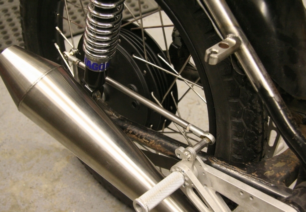
Brake linkage

I am really going for the minimalistic look on the bike so stripping everything off that isn’t required is a priority. If I could get every cable off the bike I would however I have to stay realistic. I had already machined and tack welded a new rear brake cable support onto the frame (top right corner) however after rethinking things I decided to try for mechanical linkage for rear brake actuation. You can see my mocked up linkage from my rear sets to the rear drum. The pedal feel is much better and the linkage really cleans up the look. I will have to wait till the bike is at reassembly stage in order to figure out exact linkage length since chain adjustment will come into factor.
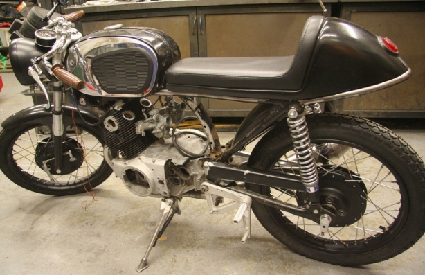
B4 disassembly

So here you have it. I think I have done as much fabricating as possible with the bike assembled. At this point the entire thing gets stripped down. Everything will then start to get prepped and refinished before reassembly will begin.
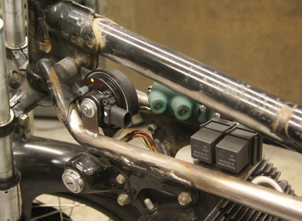
Under tank electrical

Something I never blogged about was the under tank electrical. The original horn and coil has been done away with and I added a new Dyna Coil with new mounting. The horn has been replaced with a high pitch one off a Porsche Cayenne and then I added a couple of relays to handle some of the new electrical.
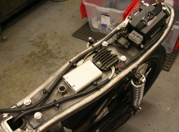
Central electrical

The central electronics have all been moved, and hidden, under the seat. Components include the electronic ignition module, charging system “regulator”, power supply relay, fuse block, starter solenoid, and battery.
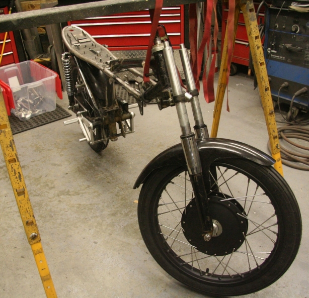
Tear down

Time to start tearing things apart. Strapping the bike to a saw horse provided enough stability in order to get the wheels and suspension off.
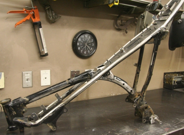
Torn down

So here it is, the bare frame. Not a single nut, bolt, or clip is left on it. Time to start laying down some final welds and clean up some existing ones.
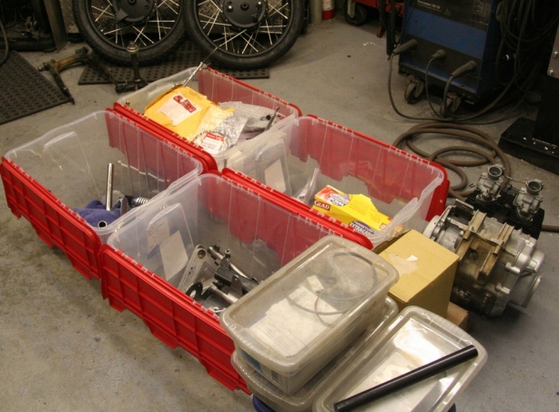
Organized components

All removed components were separated into indivduals bins to help keep things organized. A bin for powder coating, a bin for chroming, an electrical bin, and then a misc. bin.
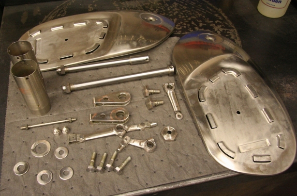
Prepped 4 chrome

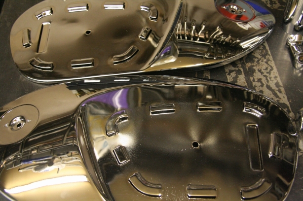
I am not a huge fan of lots of chrome however since one of the distinctive features of the bike include the factory chrome tank covers I felt it was necessary to bring some chrome highlights into the bike. I chose some hardware, brake linkages, axles, and fork seal housings to join the tank covers in their display of bling. I had a local electroplating company strip the old chrome first. I then performed some touch up on all the parts and sanded out any rough casting marks. Once prepped the components were sent back to the electroplaters.
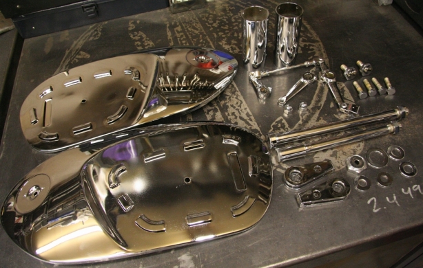
Completed chrome

Here are the freshly chromed bike components. If you look at everything to the right of the tank covers you will see that there is not a lot of chrome on the bike, just enough to help blend the tank covers in with the whole package.
Tank covers chrome

The tank covers turned out fantastic!

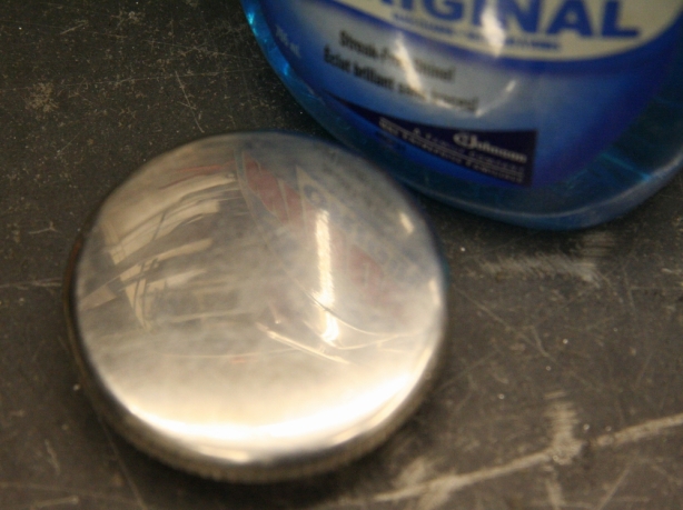
Original fuel cap

The fuel cap is stainless steel so I opted to polish it up myself. Here is the before shot.

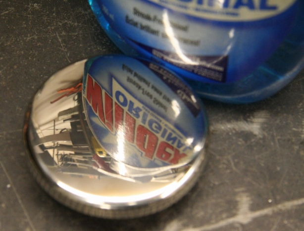
Polished fuel cap

And here is the after shot and the results of 3 stage polishing.

Fuel cap rebuild

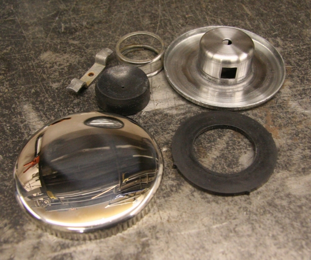
The tank cap is pressed together but I was able to “blow” it apart using compressed air. I then was able to clean all the old varnish and rust from the internal components. I was successful in pressing it all back together.
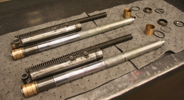
Fork rebuild

Something that had been weighing heavy on my mind was the front fork rebuild. I was unsure if they would come apart easily and I suspected I may have seal issues. Turned out getting them apart was a bit of a challenge. I needed to machine a tool in order to spin off the fork seal housings. Also trying to slide the rams out from the lower housing was not easy as they did not slide smoothly out the bores. More on this later.
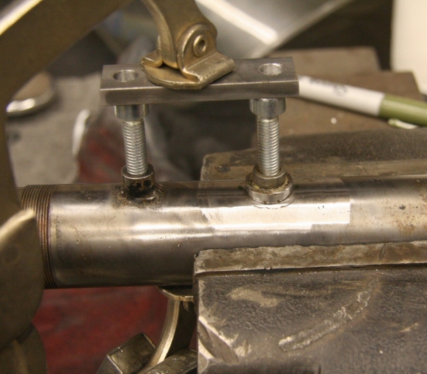
Fixing fork nut

The front fork lowers have 4 threaded spacers welded onto them, they all support the front fender however one is the nut that secures the front brake drum arm. This one was broken off at the welds. Needless to say the front brakes do not operate without the arm securing attached to the fork assembly. I used the original threaded spacer and TIG welded it back on.
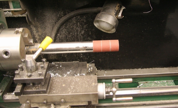
Fork hone

So here comes the story of why the forks had trouble coming apart. I knew that when I welded the spacer back onto the lower fork tube that the inner bore of the tube may distort. It turns out I was right and after TIG welding the spacer on the fork ram, and bushing, would not slide down into the housing. As I inspected a bit more closely it would appear that the factory welded spacers also distorted the tubes which is why I suspect the bushings were so hard to remove from the fork lowers. I am guessing that the factory must weld the nuts on after the rams are installed, this seems odd to me however I can not determine how they could have installed the rams into distorted fork lowers. I had to come up with a solution to help everything go together, and slide, smoothly. The fork lowers have a second tube in them to allow for spring support. This made for cleaning of the inside bore difficult. In the end I decided I would machine a pipe down enough to fit into the fork lowers. I then glued sandpaper onto the pipe to turn it into a hone.
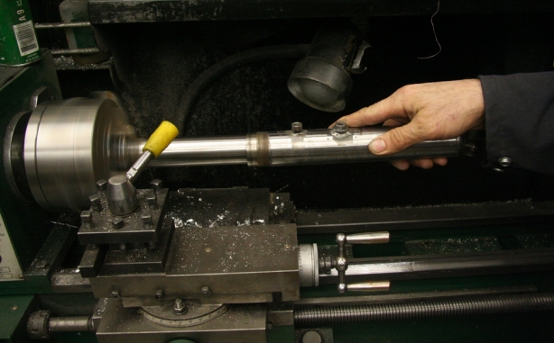
Honing the fork

Here you can see me honing the side of the fork lower which has the nuts welded onto them. I was able to take off just enough material on the inside of the fork to allow the ram to slide smoothly. Lucky for me these forks are 1965 technology and they do not possess, or require, the precision of modern engineering.
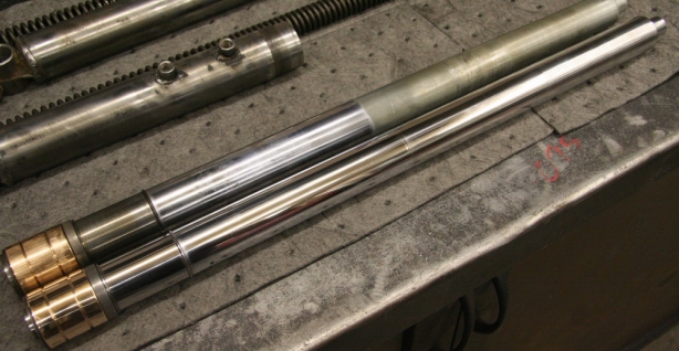
B4 and after ram

The fork rams received a good polishing to clean up some of the old wear and tear. The rams inspected to be in good order with no major nicks. The upper fork is original and the lower is one that has been cleaned up.
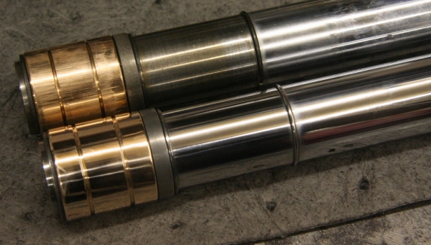
Polished fork bushing

These are the bushings that need to slide smoothly into the fork housings. You can see the scoring on the upper bushing that was caused upon removal. I was able to clean up the scoring and give them a good polish before reassembly.
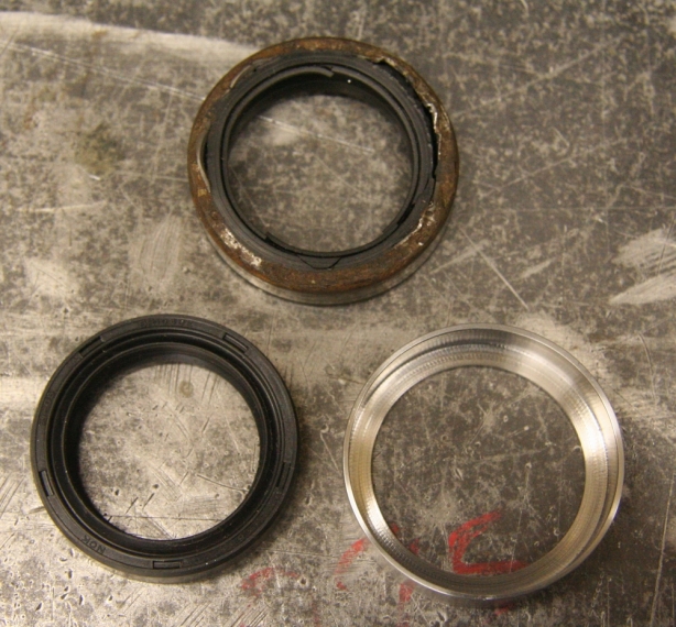
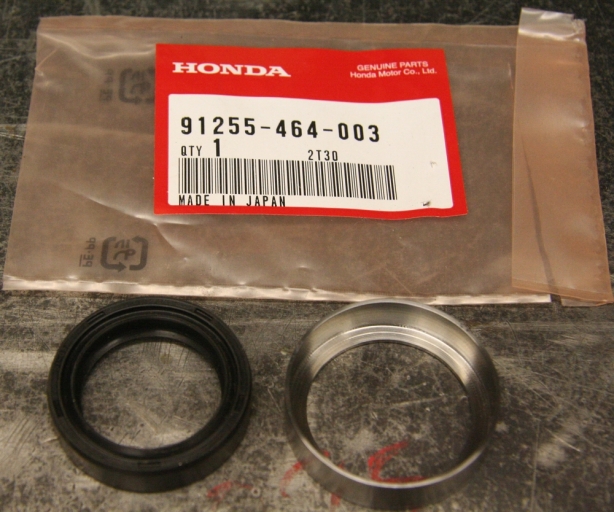
Seal compare

I have pretty much sourced every single part I needed for the CB160 project. I think I have only failed on 1 part and that is the fork seals. I was able to find a supplier however the logistics involved in actually performing the purchase transaction made it too difficult to obtain the seals. I opted for improvisation. The CB160 had 2 different fork seals. 1 for the early model (which is mine) and 1 for the later model. Turns out the later ones are still available from Honda. The difference between the 2 different years is the outer diameter of the seal. Lucky for me the inside diameters appear to be the same. The later models have a smaller OD which also turns out to work in my favor. So in order to adapt the later model smaller OD into my early model forks I opted to machine a press fit spacer as an adapter sleeve for the different seal. The top seal in this picture is the original. The bottom left is the newer seal with a smaller OD and the right is the completed spacer I machined to use as an adapter.
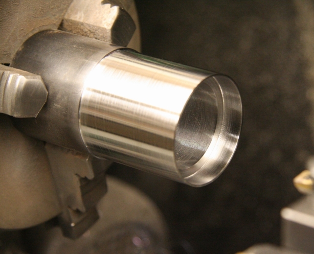
Fork seal bushing 1

I used a 1.750″ seamless pipe with a .250 wall thickness to machine the adapter from. It was hard to measure down to the thousandth of an inch in order to accommodate a press fit.
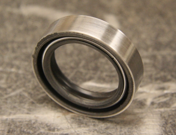
Fork seal bushing 3

This is the new style seal with the completed bushing.

Fork seal bushing 2

And here is what the seal looks like pressed into the bushing. I did not post pictures of the installed assembly into the fork tube however the press fit turned out great! Hopefully no oil leaks around the OD of the seal or bushing.
Seal housing o-rings

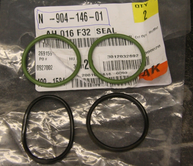
One other part I failed at obtaining was the O-rings required to seal the fork seal housing to the lower fork tube. They are a 38 x 2 mm o-ring and are no longer available. With some searching I found that VW uses the same size seal on multiple engine components including fuel pumps. I ordered a couple up from VW in hopes they would work. Turns out the fit was perfect. Problem solved.
Coating fork lower

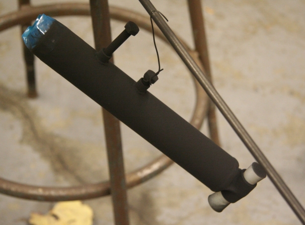
So with all of my fork issues behind me all that was left was to perform the finishing touches before reassembly. The fork lowers got sandblasted and powder coated matte black.
Fork ready 4 assembling

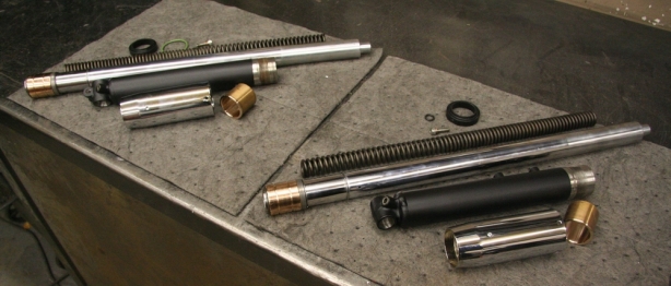
Here are all the refinished components. Seat housings chromed, rams polished, lowers powder coated, housing honed, and seals installed. All ready for reassembly.
Forks assembled

Completed forks with aftermarket bellows added to them. Another “to do ” item checked off the list.

Blasted tank 1

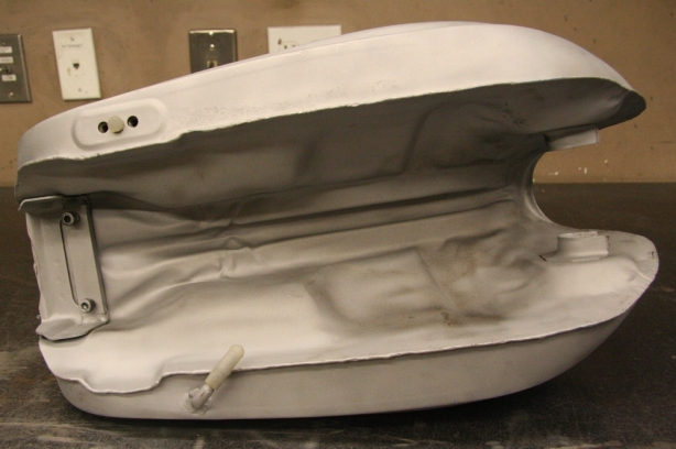
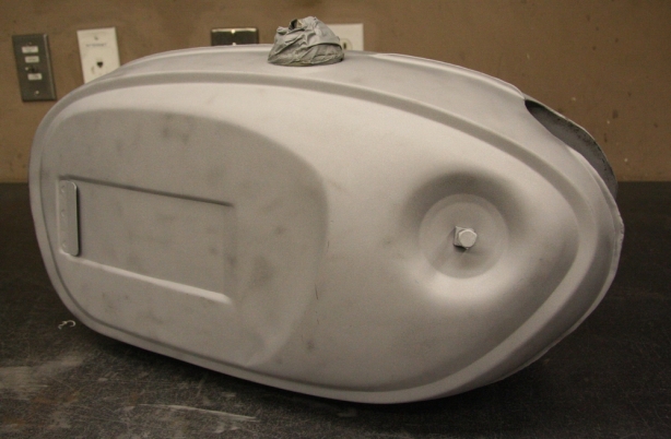
It is getting to the point where I need to get some main components refinished. I started by glass bead blasting the tank. The clean up turned out fantastic. It was stripped of all the old paint and rust and upon inspection it would appear the tank had no dents or damage. There will be very little body work required.
Blasted tank 2

The underside of the tank cleaned up great too. Totally stripped of all 1965 color.

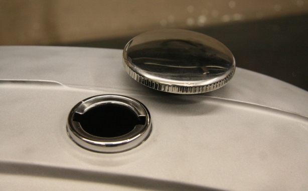
Polished tank filler

I thought that polishing the filler neck would give a more finished look plus it will tie in nicely with the polished fuel cap.
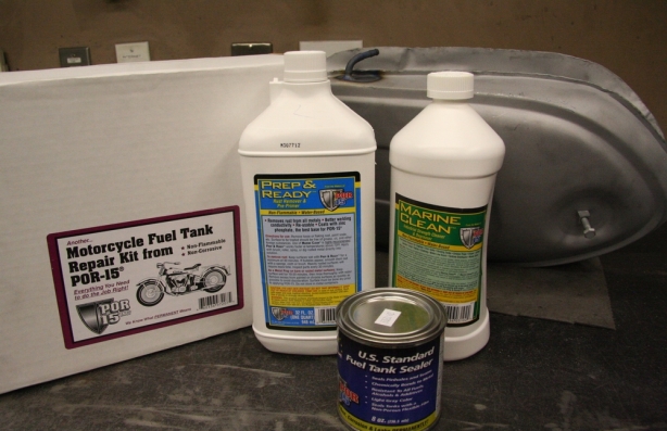
Tank repair kit

The tank had a lot of rust in it and was going to require some serious attention to get it all cleaned up. Earlier I had ordered a POR-15 fuel tank repair kit knowing I was going to have to attack my problems with chemicals. I used the kit however not exactly as the directions stated. Here was the sequence I used to achieve fantastic results;
1. Rinsed that tank with Marine Clean for 15 minutes
2. Rinsed the tank with CLR for 15 minutes.
3. Added approximately half a cup of glass beads and 2 cups distilled water and shook vigorously for 15 minutes.
4. Rinses and pressure wash the inside of the tank
5. Added another half cup of glass beads and halve a bottle of Prep and Ready and shook again for 15 minutes
6. Rinsed and pressure washed
7. Added straight Prep and Ready and soaked for half an hour while repositioning.
8. Rinsed and pressure washed.
9. Dried the tank for 4 days which included multiple sessions with a heat gun
10. Coated the tank with a sealer.
The whole process took time however the results were great. The tank cleaned up inside to bare metal and there were no leaks before, or after, the sealer.

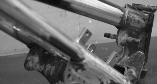
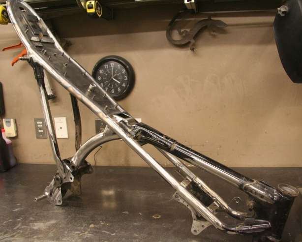
Prepped frame

Although this picture is not overly exciting it shows the results of hours of work. I ground lots of the old, ugly, factory welds and redid them with TIG. All the crucial visual areas got ground and sanded smooth. The frame is now ready for sandblasting, a bit more touch up, and then paint.

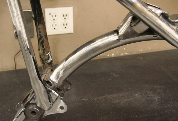
Cleaned up downtube

This is one of the highlights of the bike. The down tube. For me this section of the frame needs to have a very clean look to it. A lot of the factory holes were filled in and then the welds were sanded smooth.

Title rear wheel

The game plan with the 65 Revive Honda CB160 cafe racer build was to perform as much of the fabrication work before tearing the entire bike apart. Lots of people choose to strip the bike down first then perform the modifications. I want to keep the bike together as much as possible therefore I can ensure everything will work in harmony with one another and that way there will be no unwanted surprises during final reassembly.

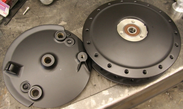
The finishing stage will be the final chapter in the rebuild however in the case of the wheels I was forced into performing the detail work now. The reason is that fender mounting requires that I have the proper, and properly inflated, front tire on the bike. Since I didn’t want to mount up my new tires on old rims I opted to tackle the rim rebuild at this stage in the game.

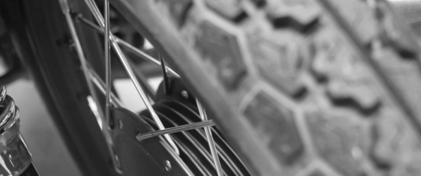
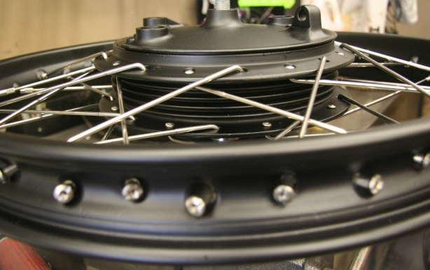
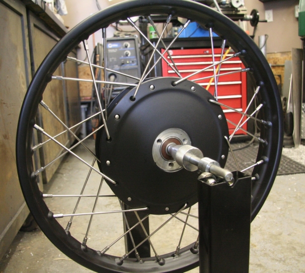
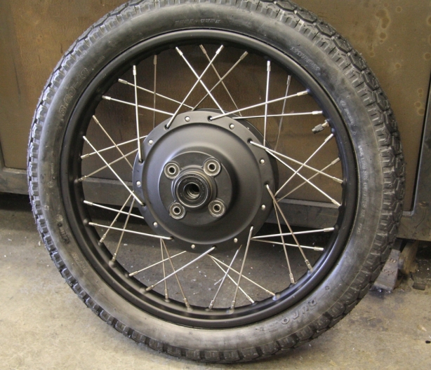
The plan was to abandon the factory chrome look of the rims. The hoops and hubs will get powder coated matte black and then will be laced back together using stainless steel spokes and nipples.

I have already collected all my parts including tires, tubes, rim strips, spokes, nipples, bearings, bushings, and brake hardware. Therefore all that was required was some time and labor.

I’ll run you through the details using visuals. The rims turned out fantastic. The powder coating went as well as I could have expected. Some parts had some minor flaws however the result equalled my experience. The hoops trued up and tensioned up and I was able to mount the tires without causing damage to the finish. Now I can continue on with more fabrication.

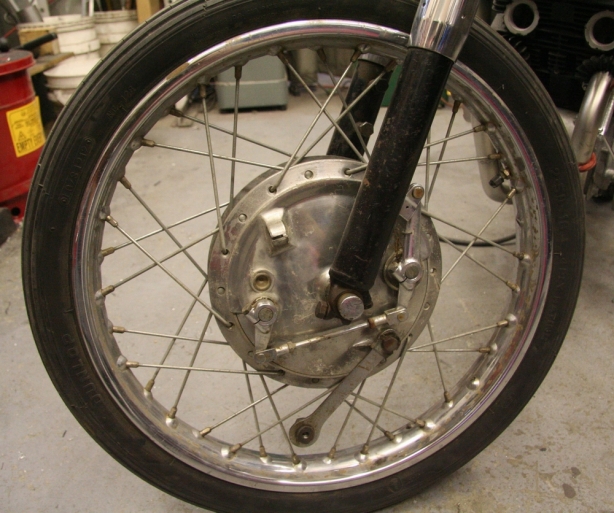
OEM front wheel

Here it is, the stock front wheel. The plan is to powder coat the hoop and hub matte black and then replace the OEM spokes with stainless steel Buchanan spokes.

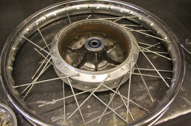
Front de-laced

Front rim getting de-laced. The hub and hoop both inspect to be in good shape.

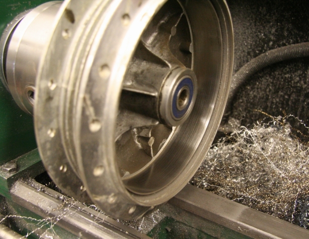
Front drum touch up

Set the drum up on the lathe to clean up the brake friction surface. No cutting required, light sanding did the trick.

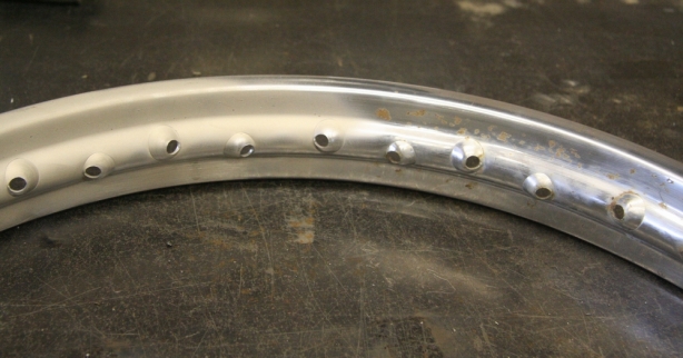
Hoop blasted half n half

Initially I thought I would have to strip the chrome from the OEM hoops before powder coating. After doing some research I figured there was no reason I couldn’t powder over top of the original chrome. None of the factory chrome was flaking off and it was still all intact. I took the sandblaster to the bare hoop to rough, and clean, the original chrome. The left is sandblasted and the right is factory.

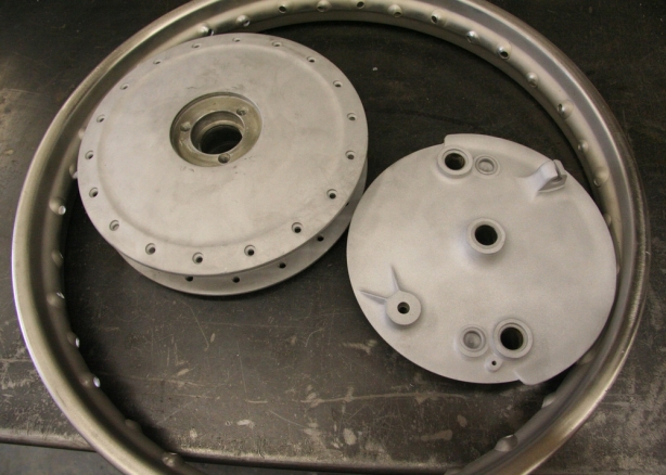
Wheel prepped 4 powder

All the wheel components have been prepped and blasted. Just need to be cleaned and then the power fogged on.

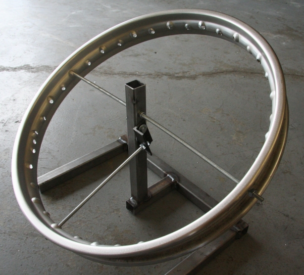
Hoop jig

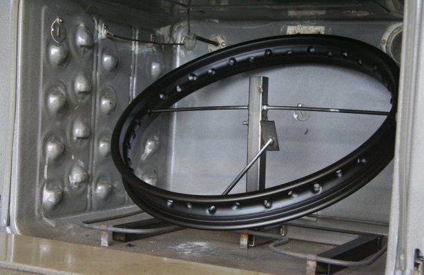
The 18″ hoop just barely fits in the powder coating oven. It needs to be held at just the right angle in order for it to fit. I constructed a crude jig to hold the rim just right for baking.

Hub fogged

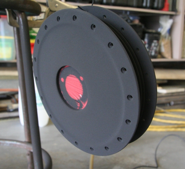
Here the front hub has been fogged with matte black powder just before it gets placed into the oven.

Hoop baked

You can see the tight fit of the rim in the oven. The rim has been baked and is now in cool down stage.

Hubs matte black

Completed front hubs. Looks good.

Buchanan's

I was in the area of Azusa California so I took the opportunity to stop in at Buchanan’s to order and pick up my stainless steel spokes. Great service and great product. Very helpful staff.

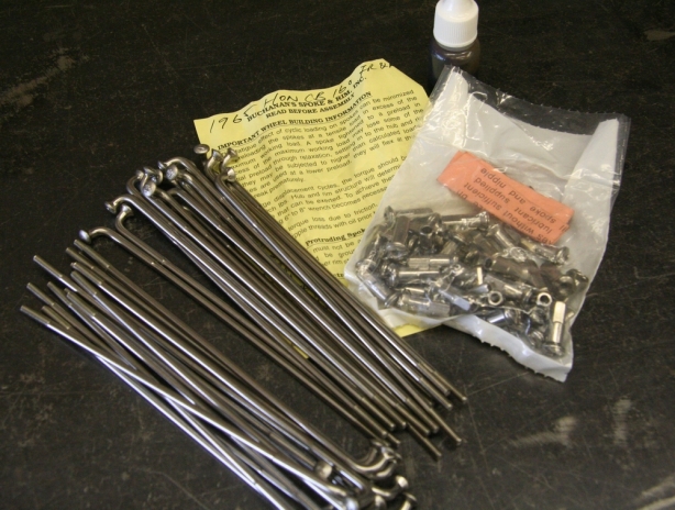
Buchanan's spokes

Spoke set for the CB included double butted spokes with stainless nipples. Front and rear rims use the identical spoke lengths.

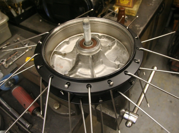
Front rebuild

Starting to lace and rebuild the front rim.

Front laced

Initial lacing complete, onto the trueing and tensioning.

Front trued

The rim trued up and tensioned up beautifully. Worked out great.

Before and after wheels

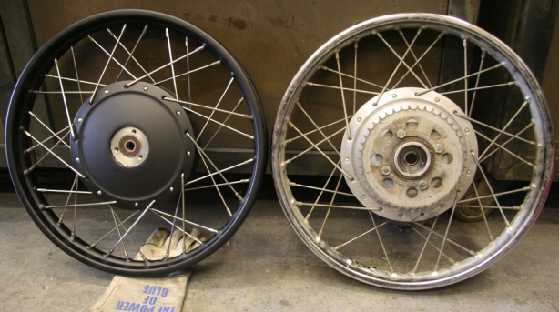
New matte black front rebuilt wheel compared to the OEM rear wheel.

Cutting out bushings

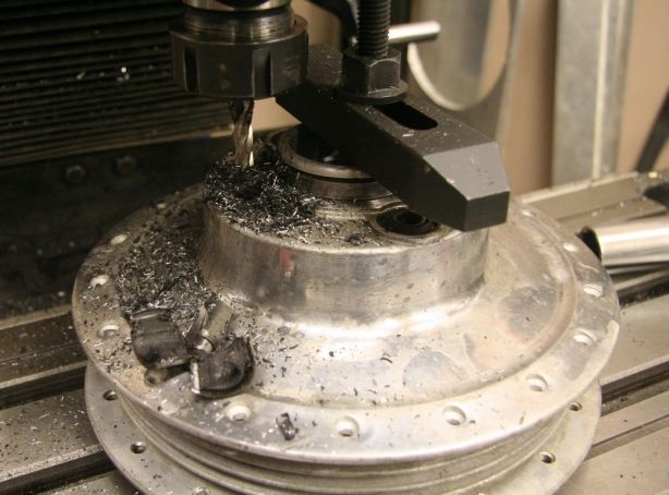
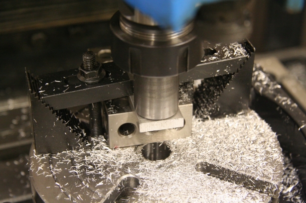
With the front rebuilt it was time to complete the rear wheel. The sprocket is mounted into rubber bushings and I had new ones to install. The factory bushings are pressed into a blind hole. I opted to mill the old bushings out.

Pressing in bushings

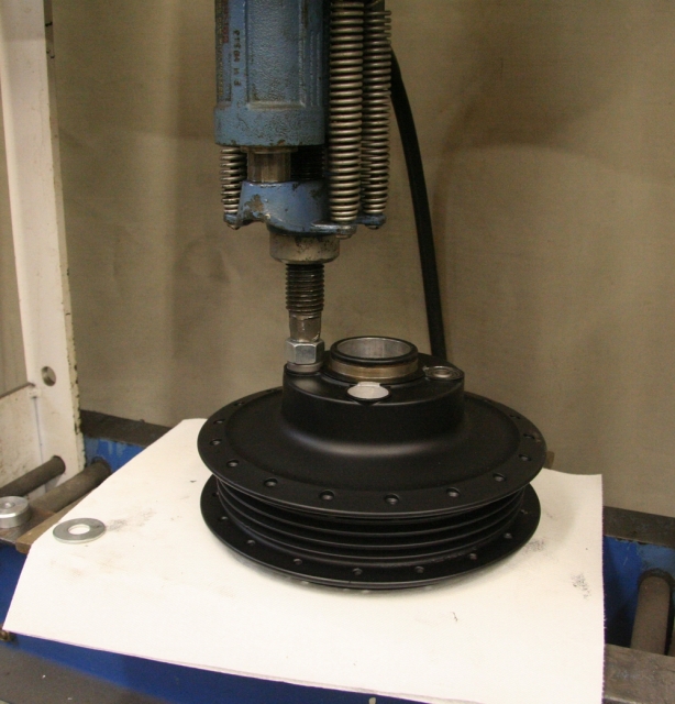
With the rear hub prepped and powdered I was able to press in new sprocket bushings.

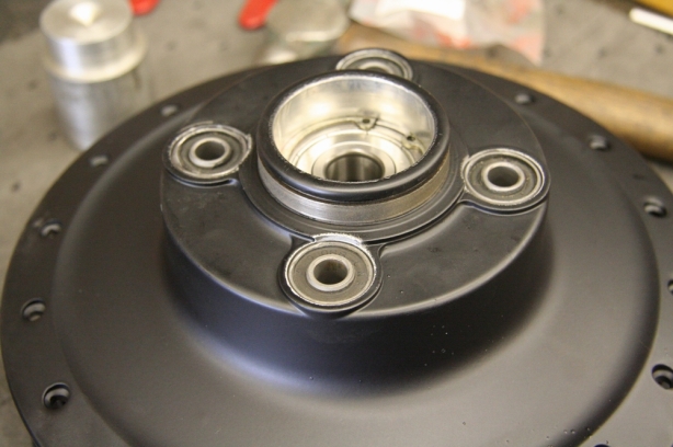
4 new bushings

Rebuilt rear hub with new bushings and new bearings.

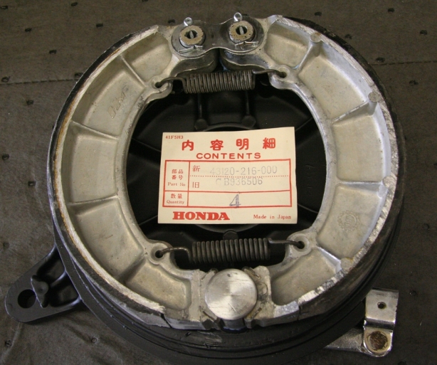
New factory brakes

Front and rear both got a new set of brake shoes. I was able to score some NOS shoes for the rear.

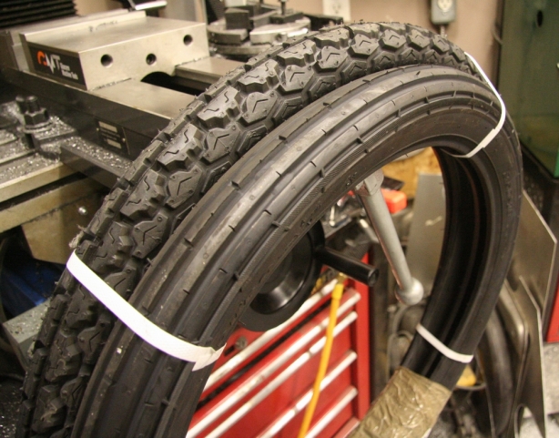
New tires

The rubber was harder to find then I initially expected. I settled on some Duro tires which had similar tread patterns to the factory tires. I went with a 2.50-18 front and a 3.00-18 rear.

Rear wheel complete

The completed rear wheel with the new rubber mounted.

New wheels

Final shot of the wheel rebuild. I had to sweep out the shop so the bike got to see daylight for a brief period.

Title mirror

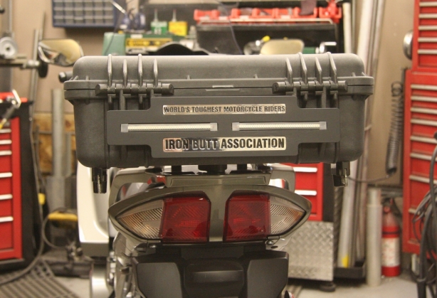
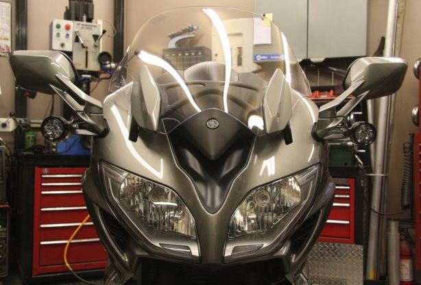
So I continue to work my way through the FJR1300 Gen III retrofit project. Previously I was able to machine the name plate and LED light holder that would eventually get mounted to the back of the Pelican case. Next it was onto building a Pelican Case mount as well as try and come up with some way of mounting a couple of Clearwater LED driving lights.

I continue to strive for professional looking results and when mounting accessories to the bike it is important to blend the mounts in with the flow of the bikes lines. Nothing looks worse then something that simply doesn’t appear to belong. Subtle and discrete is usually a good thing and the less flashy and obtrusive I make it I think the better it will look.

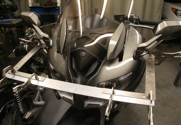
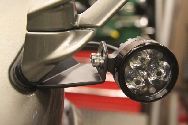
So as my dad and I search for a place to mount the front auxiliary LED lights to it soon becomes evident that there are not too many options, at least none that would look good. Finally settled on trying to fabricate a couple of brackets that will get sandwiched between the base of the mirror mounts and the fairing. After much looking and measuring it would appear that the odds may work in my favor. Although I wasn’t convinced the plan would come together in the end there was enough evidence presented that would suggest the efforts verses the failure ratio was one worth pursuing.

So the bike was hauled into my garage and the fabricating began. I had a basic idea of what I wanted to accomplish however the aspect that complicated it all was I was working with 3 odd ball X Y, Z, angles. The angle of the mirror mount was situated in such a way that I needed to compensate for the angles and build a bracket that would eventually be square, plumb, and level.

I stock old cereal boxes in my garage because the cardboard is good for building templates from. So I began by building a cardboard sample of the LED light bracket in order to help determine the angles that would be required. Once I mocked up the cardboard I switched over to a scrap piece of steel and build a crude mount to ensure my efforts would not be wasted. Once I determined the proper angles I began building to good brackets.

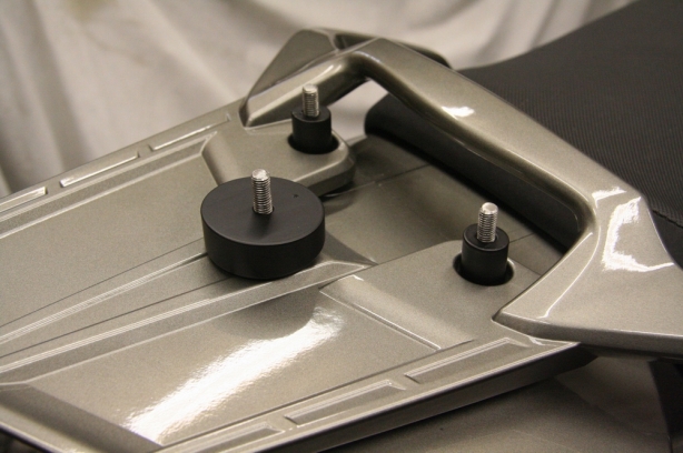
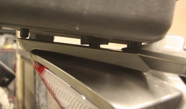
As far as the mounting of the Pelican case I simple machined some spacers to fit in place of the existing factory rack hold down hardware locations. I cut the spacers at an angle to ensure that the mounting of the case would remain parallel with the back rack.

Once everything was fabricated the complete works got a glass bead blasting and then everything was fogged with some matte black powder coating. In the end I think the completed project worked out well. The front lights look super clean and super factory looking. The matte black finishing blends everything into the bike and prevents things from standing out as thought they don’t belong. My dad is happy and has since taken back possession of his bike and has everything wired up and working. He put his first 100km on his new bike today and was happy to report that everything is working 100%. On with the pictures…

Cheat arbor

I built a cheater arbor to help speed up the set up when needing to mill a radius. The arbor is a chunk of cold rolled round bar with the same radius as I require. I center the rotary table to the mill head and then clamp down my work piece once I have my arbor lined up. It isn’t highly accurate but I would guess that I am within .010″.

Bracket radius

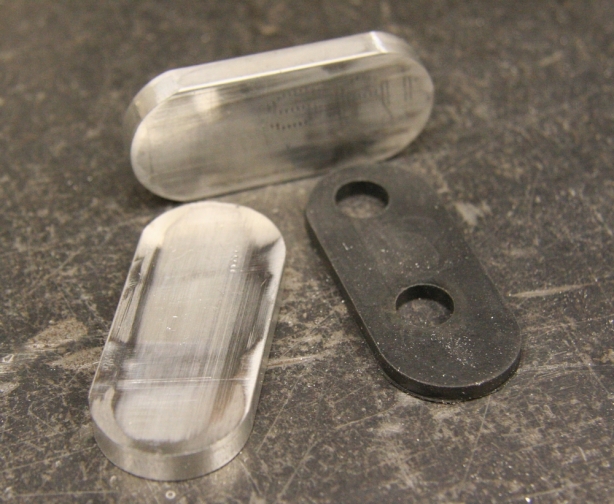
Here are the results of my laziness. The radiusing of the mirror spaces work out great. They were cut from 1″ x .250″ 6061 aluminum.

6061 Mirror spacers

Here are my roughed out mirror base spacers. The black base gasket shows some resemblance, this is good.

Bracket taking shape

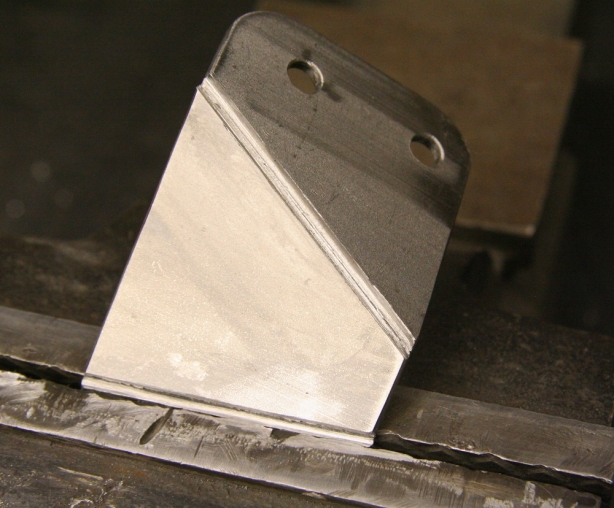
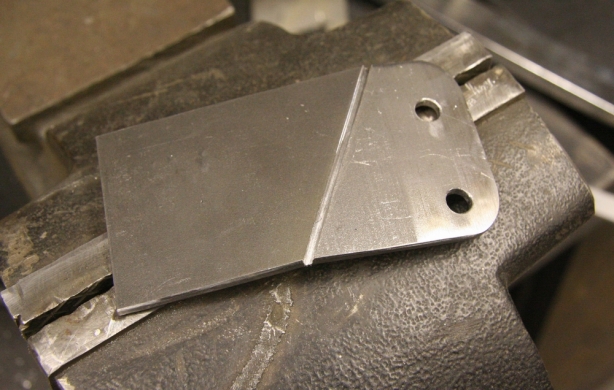
This is one of my good LED light mount brackets starting to take shape. I scribe my bend angles with a cut off wheel. This way I get a super clean inside bend line and it allows me to weld the exposed cut on the outside of the bend and clean it up. It not only adds strength but also looks ultra pro.

Bracket leveling

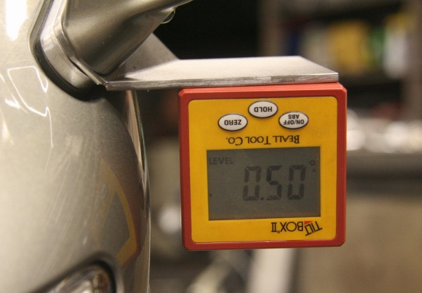
Much time was spend mocking up the brackets to ensure that my X,Y, and Z coordinates were all on even planes. Here I got within .50 degrees of level.

Perpendicular measurement

The lights will be adjustable vertically but not horizontally therefore the brackets need to be fabbed accurately. I used a couple of squraes and a staright edge to help determine what the “straight ahead” position.

Cutting vert adjusters

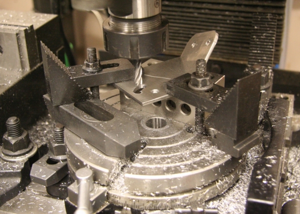
Before I performed the final bend on the brackets I milled out the adjustment slots to allow for vertical adjustment of the LED lights.

Bracket basics

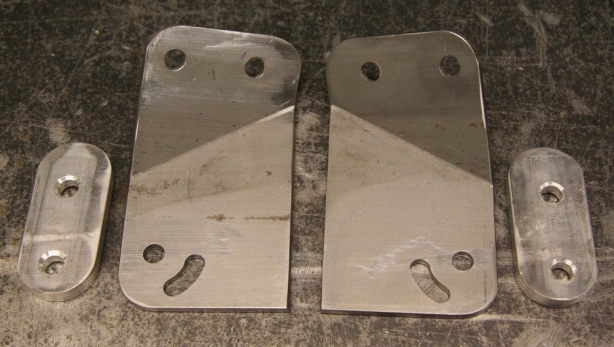
Here sit all the LED light components minus the final bend, and trimming, of the brackets.

Bending bracket angles

Final bends. All that remains is welding and grinding of the scribe lines.

Wire channel test

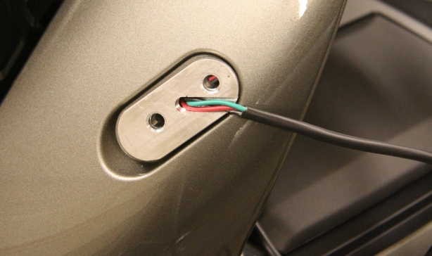
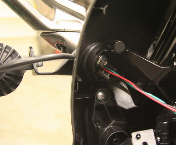
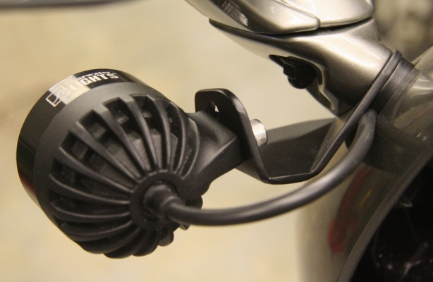
In order to make the bracket look super clean I needed to be able to hide the wiring. I milled a channel into the base spacer plates and the drilled a hole in order to feed the LED wiring in under the mirror assemblies.

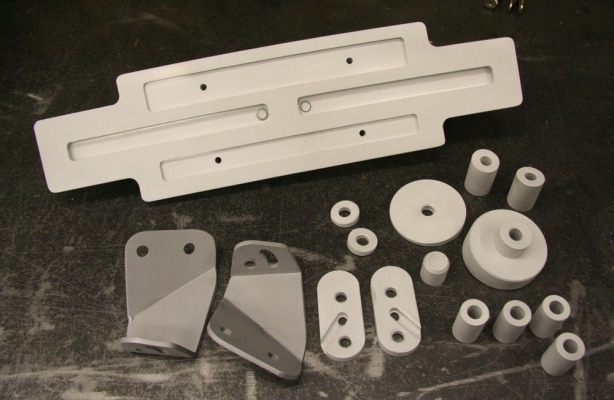
Brackets and spacers blasted

So here you have it, all the fabricated components glass bead blasted and ready for powder coating. I never posted pics of the Pelican case spacers however it is fairly obvious that I spun them up on the lather out of aluminum.

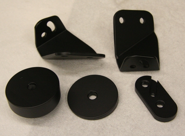
1st batch coated

First batch of matte black powder coated components.

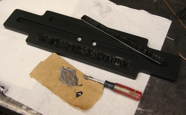
Plate epoxy

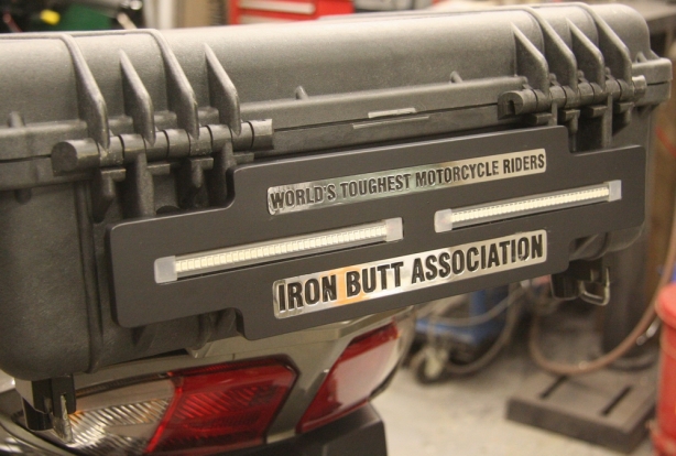
With the Pelican case plate coated I was able to epoxy on the “Iron Butt” name plates.

Pelican case spacers

Here the Pelican Case spacers are installed on the rear of the FJR’s rack.

Pelican case support

A side shot of the mounted Pelican Case shows how the angled spacers allow the case to run parallel with the factory rack. Looks clean.

Completed Butt plate 4

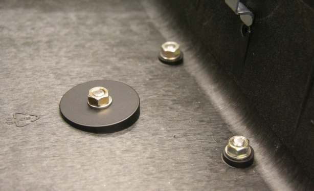
The case gets bolted to the spacers from the inside. In order to accomodate the parallel fit some angled washers were machined.

Completed Butt plate 3

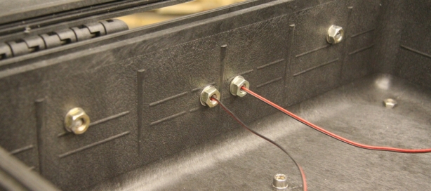
This is the inside shot of the mounted name plate. The 2 center studs were machined out to allow for hiding of the LED wires.

Completed Butt plate 1

Light bracket 1

Light bracket 3

This shows the routing of the wires in behind the mirror base. There is still a plastic fairing cover the dash assembly.

Light bracket 2

Tucking the wiring of the lights in under the mirror mounts worked great.

Mounted lights

Completed Butt plate 2

Title Porsche

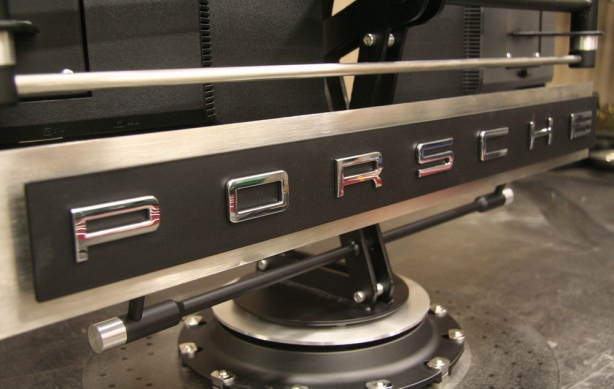
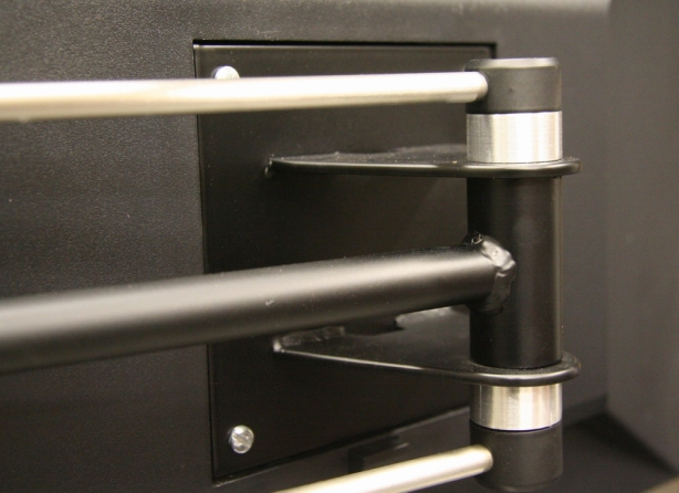
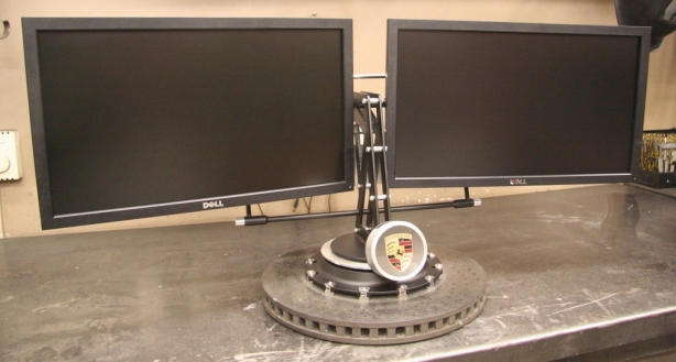
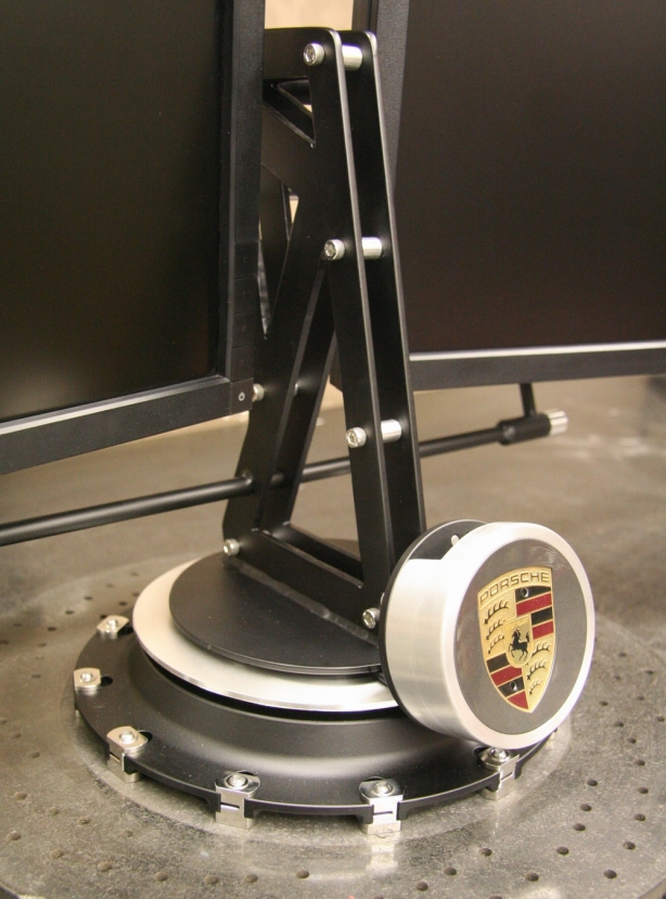
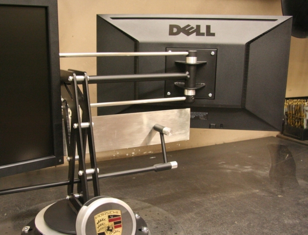
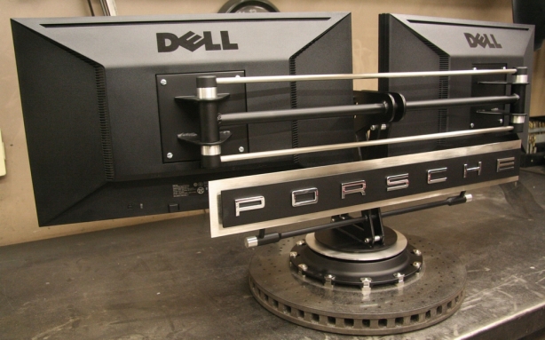
Well it was time to get into the finishing stages of the Porsche dual monitor stand project. Up until this point all the fab work had been completed and it was time to disassemble, clean, and put the finishing touches on. I admit I enjoy the fabrication work more than the finishing however there is much to be said for the satisfaction one gains from seeing the project come together in the end and reach completion.

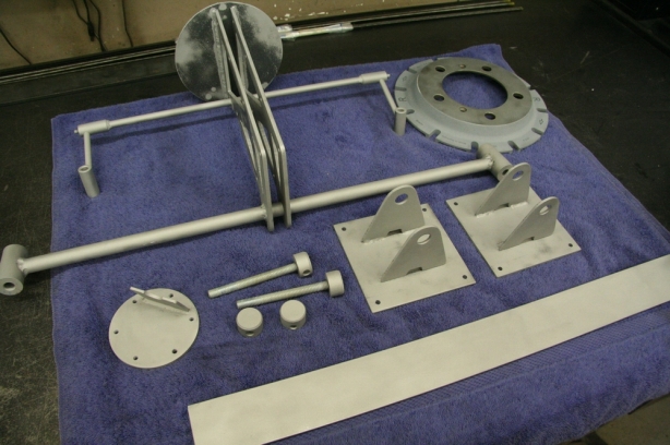
I had a specific finish in mind for each component of the stand at time of inception and the game plan never wavered. All the components received the finishing touches that were original brainstormed. Basically it came down to three processes. Powder coating, brushing, and polishing.

Disassembled and blasted

All the powder coated components were glass bead blasted and cleaned prior to getting fogged.

All the components that were to be powder coated needed a good cleaning and glass bead blasting as a preliminary step prior to fogging of the powder. The stand was completely disassembled, and few welds touched up and then all the mild steel components were tossed into the blast cabinet for an exfoliation session. Once they were rid of all external toxins it was time to shower then with some denatured alcohol and prepare them for the sprinkling of powder. My powder color choice was really not a choice at all. I felt as though I had no options except to go with the flat black powder (the same stuff I used for the CB160 engine). When I look at the marketing material, and finishes, Porsche uses in the vehicle showrooms and service reception areas the presence of brushed stainless and flat black are fairly evident. As much as it would be nice to through on a splash of color I opted to stay conservative, and with the original plan.

Black matte powder coat

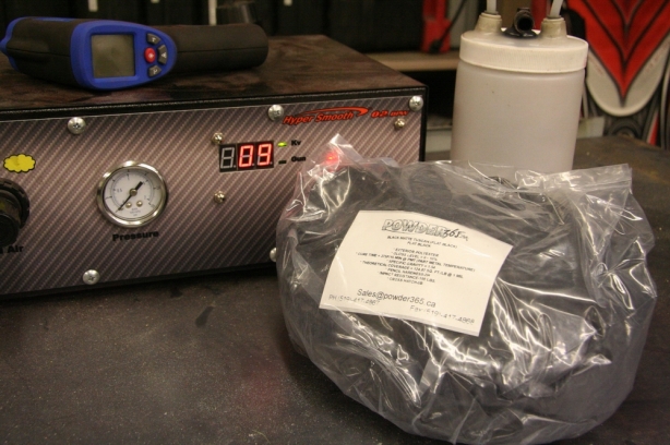
Opted to go with the matte black powder. Ordered up 4 more pounds since this is the same color I am using on the CB160 cafe racer build.

Main support powdered

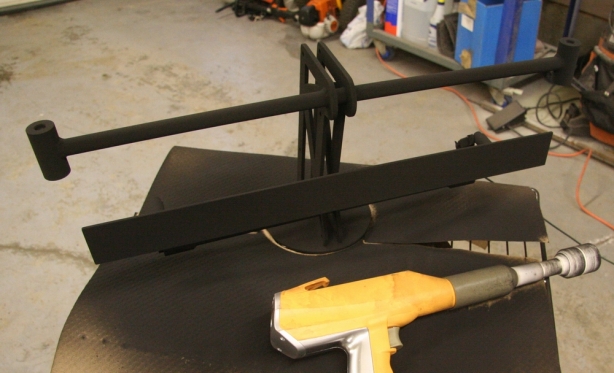
I bolted the stand to the oven rack so that I could just slide the complete assembly into the oven. I covered up the rack while spraying to try and prevent me from powder coating it.

Just about all of the stainless steel and aluminum were finished with a brushed look. I have always struggled to try and develop a good technique for brushing stainless. It is important to achieve a constant, and even, brushed look. The crucial piece that required this treatment was the 3 inch stainless flat bar that was backdrop to the “Porsche” logo. I was starting off with a rough finished piece of stainless. I opted to install a brand new 180 grit sanding belt onto the 6 x 48 sander and proceeded to work down as much surface area as I could fit onto the sanding belt. It hard work and it takes its toll on the horsepower but in order to reach the level of finish I wanted it was important to work the stainless down as whole. The 180 grit paper was working however I decided I would see how a 120 grit approach would work. I swapped over the belt and continued to work the metal down. I think the brushed look of the 120 grit gave me the look I was searching for so I decided to go for it. In the end I was very pleased with the end result.

Powdered rotor hub

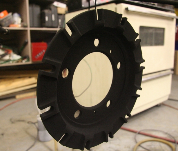
This is a shot of the ceramic rotor aluminum hub just before it is going into the oven for baking.

Baking the goods

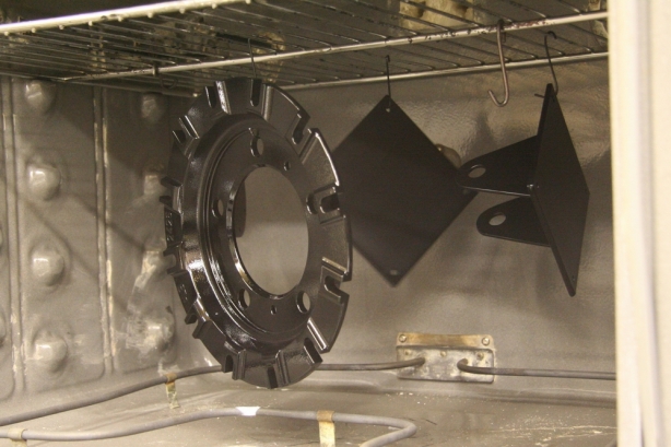
Powder is starting to flow in nicely. 15 minutes at 375 degrees PMT.

When it came to giving all the aluminum components the brushed look they all got mounted up on the lathe and all received hand sanding to achieve the look. Since the aluminum is much softer then the stainless I found a 320 grit finish was better suited to tie the 2 different metals in together.

Polishing hub pins

Performed a single stage polishing of all the rotor to hub pins. The slight gleam will help them pop against the matte black.

Hub pin set

Completed set of polished hub pins.

Hub pins installed

The pins were a bit tight sliding back into the rotor hub because of the thickness the powder coating added. A bit of persuasion was all that was required.

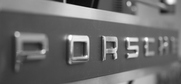
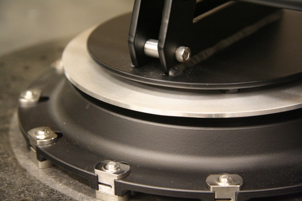
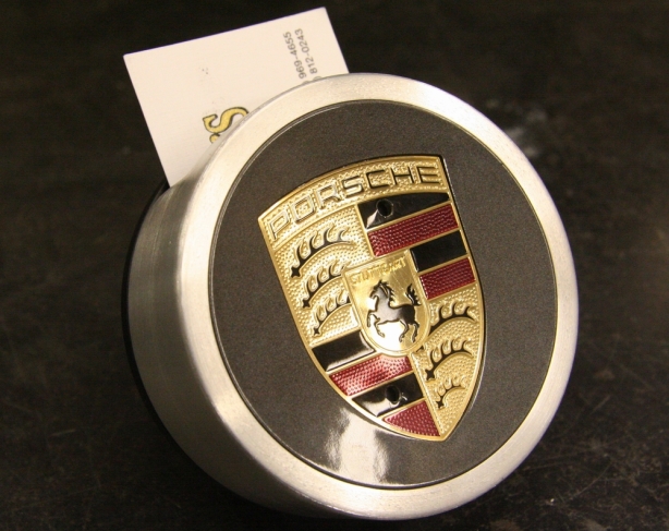
As far as the polishing goes there was not much to do. I always try to work in odd numbers if possible. In the case of the finishes I had black powder coating and brushed surfaces. Adding in a polished dimension would bring my even to odd and help create e a more pleasing look. I also opted to polish because of the purchased Porsche emblem. It was only available in a chrome/polished look and therefore I did not want to leave its finish all unto itself. I chose to polish all the locating pins of the ceramic brake rotor. I did not polish them to a chrome finish but opted to just “gleam” up a bit. The only other part of the project that was left with a polished look was the rim of the base aluminum disc that sits on top of the rotor. It is only about 3/32” that is polished however it is enough to add a subtle highlight.

Brushing aluminum base

Giving the base aluminum plate a brushed finish.

Nasty hardware

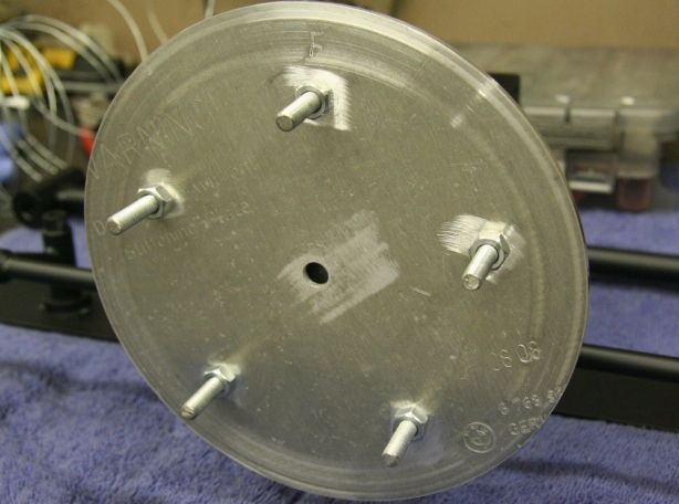
Here is the bottom of the base where it will bolt to the rotor hub. It’s not pretty but it is functional. You can see the BMW logo stamped on the bottom right corner of the plate.

Porsche emblem install

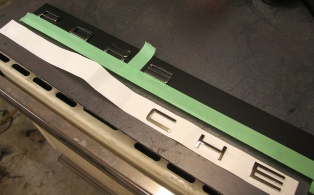
I taped off and mesured out the location of the Porsche emblem install on the front name plate.

Before and after SS

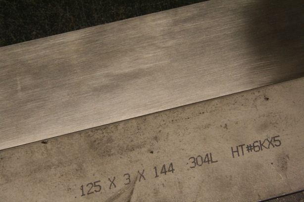
This is the stainless steel backing plate for the name plate. The top plate is the finished brushed product, the bottom plate is the finish I started with. Lots of grunt work standing in front of the belt sander.

Gel feet

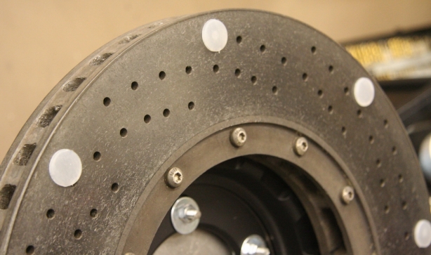
Applied gel feet on the bottom of the rotor to help protect the desk surface that it will sit on.

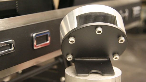
So with all the components in a finished state all that was left was reassembly. As usual the reassembly takes the shortest amount of time but is also, usually, a highly satisfying part of the project. Too bad it is short lived. With it completely assembled I was able to stand back and determine if the end result beared any resemblance to the originating idea. I would say it came out better then expected. I had my doubts during the fabricating process whether or not I had possibly taken a wrong turn with the design. I was not sure the “Porsche” nameplate was going to blend. In the end I think it all came out fine. The combination of straight lines, flat black, and brushed highlights brings it all together. I can only hope that the dual monitor stand will meet my friend’s approval. As for me it is time to clean up the shop and regroup. I think it is time to get back onto the 65 Revive project. Not sure what will be next, perhaps I will be in the mood for some exhaust fabrication. For now I will leave you some pictures of the finished project.

Monitor completion 2

Monitor completion 3

Monitor completion 4

Monitor completion 5

Monitor completion 6

Monitor completion 7

Monitor completion 10

Monitor completion 9

Monitor completion 1

Title rotor

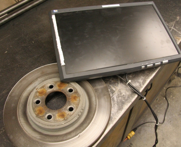
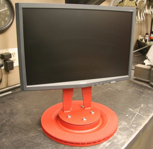
It’s been awhile since I performed a quick afternoon project but it so happened that one fell into my lap recently. A friend had scrounged up a used LCD computer monitor at his work that he wanted to use as a second monitor for his work station. He works in a shop and has his computer situated on top of a rolling tool cart. Well this monitor that had been dragged out from the bottom of a bench was lacking a stand but otherwise was a perfectly good functioning unit. So the task at hand was to build a monitor stand.

The criteria were fairly basic. Had to be cheap to build, solid enough that the monitor would not accidentally get tipped off the cart, there was no need for angle adjustment and just needed to have the screen set vertically, and the base of the monitor needed to be 6.75 inches from the table height. No Problem! The objective here was to build something quick and cheap and as long as the function was there the fashion would not be a factor.

First up was collecting the materials. Needed a solid, heavy, cheap base so an old Jaguar brake rotor would do the trick. The remainder of the stand would be built from spare metal I had laying around the shop. The design? What design! I decided to let the plasma do the walking and see what shape the stand would morph into.

Monitor and base

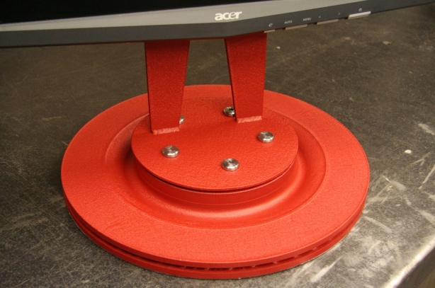
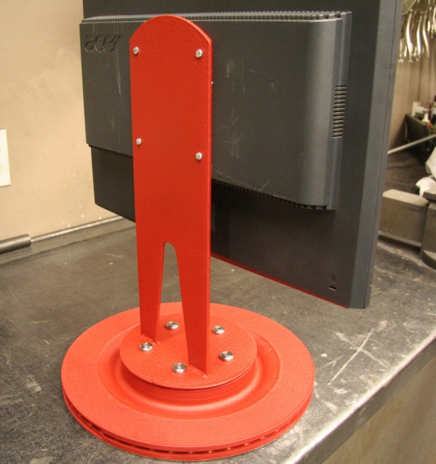
No sense in elaborating on the details. The pictures will lead you through the highly complex build as you will see that a lot of time and precision was put into the build . It was a mindless couple of hours in the garage which is just what I needed. The stand turned out great and the function performs to spec. The red wrinkle matches the tool cart and the stand even sports a ”garage” look to it. Mission accomplished!

Fabbing the vert

The veritcal support was made from a section of 5″ x 1/8″ flat bar left over from the fireplace pergolia project. The top was radiused using the plasma cutter. Here a 1″ hole is drilled as to act as the splitting into two legs.

Trimming the vert

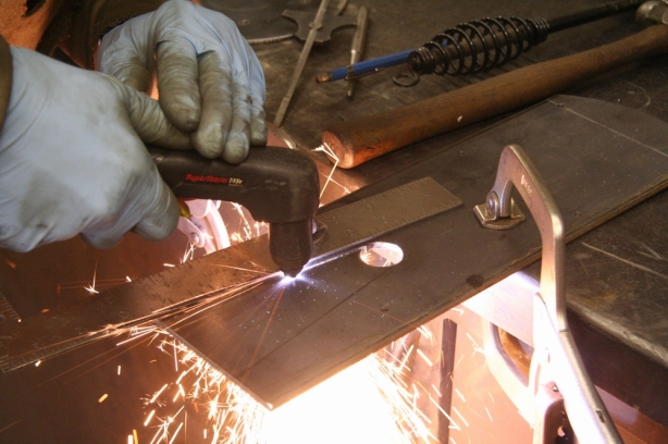
Legs get trimmed out with the plasma. I love that thing! Slicing metal helps make up for what I might be lacking in testosterone levels.

Ready 4 tigging

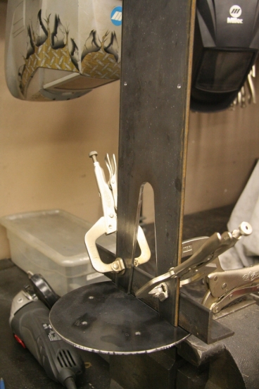
Here I have the vertical support mocked up on a circular base. The clamped angle iron is a quick and easy way to ensure I have a good 90 degree angle. The base was a chunk of steel I had left over from my gazebo table build.

Joined to base

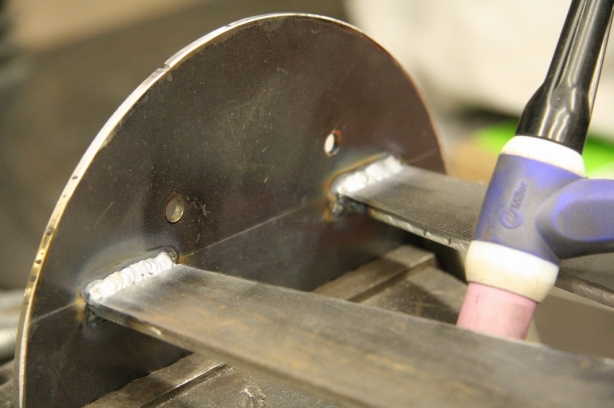
Ran a couple of TIG beads to join the couple in holy moltenry.

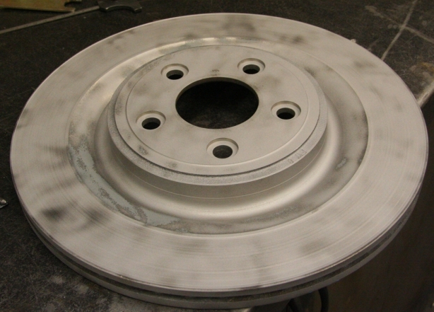
Blasted rotor

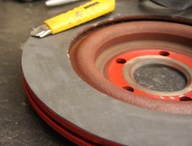
The old Jaguar rotor got a quick glass bead blasting. The rotor was fairly worn and the ridges were a bit deep however if I cleaned it up then the project would no longer be quick and easy and I would have suffered failure.

Wrinkle red powder

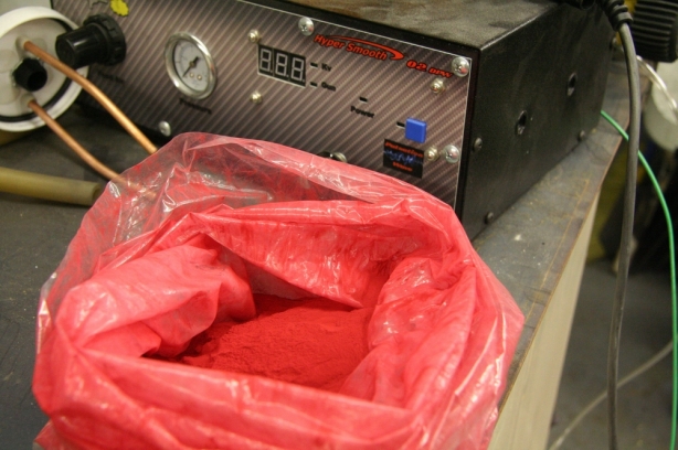
Decided to lay down some wrinkle red powder that I had as extra.

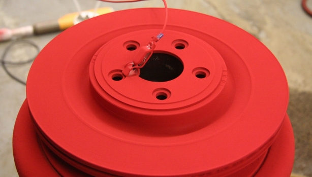
Coated rotor

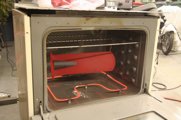
Here the rotor was coated and ready to get slid into the oven at 375 degrees for 15 minutes PMT

Baking the vert

The vertical support was powder coated to match, here the baking session is just finishing.

Rubber base

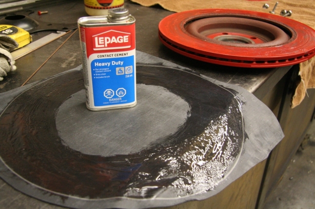
I didn’t want the brake rotor base to scratch the top of the tool cart so I decided to adhere a chunk of fish pond liner to the underside of the rotor. I used contact cement to secure it. BTW contact cement eats powder coating, who would have thunk.

Rubber base installed

After the rubber base was glued on the edges were trimmed up, came out pro looking. Too bad no one will ever see it.

Cleaning up bolt heads

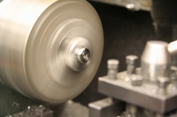
I had some funky flat head 6mm torx bolts in the bolt bin so I faced them on the lathe to get rid of the production stampings and then gave them all a quick polish.

Monitor base 2

So here you have it, quick and dirty but funtional and having met all the desgin specifications.

Monitor base 3

Monitor base 1

So I have hit a bit of a wall with the 65 Revive engine rebuild. I had ordered a NOS timing chain roller off EBay about 4 weeks ago and I still have yet to receive it. The problem is that with the upper and lower cases assembled the next component to go in is the roller. Every day I walk out to the mailbox in anticipation of receiving my roller yet every day I am faced with disappointment. I suppose I will hold on for awhile yet.
So here is everything required to get the 160cc twin running on the stand.

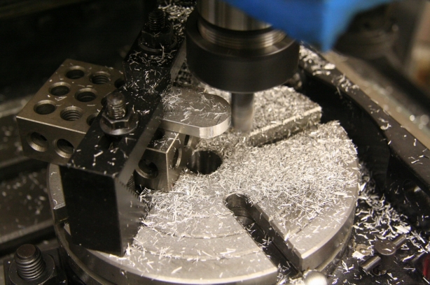
Drilling out the battery mounts on the mill.

Since I am stalled out with the engine rebuild I decided to turn my attention to other areas of the rebuild that eventually need to reach completion. The idea is to get the engine running on the test stand. I don’t want to put the engine back in the bike to start it up since there are so many other unknown issues. I decided that a few hours out in the garage would prove to be time well spent by fabricating the required external components needed to get the engine running.

Machining down a 1.000″ 6061 aluminum rod to match the handlebar diameter in order to be able to mount the throttle assembly.

Using the coil as a spacing guide in order to drill the mounting holes accurately

I started by collecting everything that would aid in providing life support to the 160cc twin. I have an old, but good, test battery. I also gathered up an ignition switch, some fuel tank components, the coil, rectifier, and throttle assembly. With all the pieces laid out on the bench I performed a 2 minute engineering session and came up with a plan to build myself a power tower.
Fabricating the ignition switch mount.

Here are all the fabricated components for the power tower. Time to put the finishing touches on them and then perform final assembly.
The idea is to weld up a stand that would bolt to my existing stand which will hold all the life support components. So I rummaged around and picked out pieces of scrap metal from my piles and started to cut and weld. I did a bit of machining for both the coil spacers and the throttle perch. Both components were cut from 6061 solid rod.

A quick mock up of all the components ensured that everything would fit.

I will let the pictures tell the story of how the power tower came to be. In the end everything came together as a functioning unit except for the one component I forgot to incorporate. I neglected to make room for the starter solenoid; it still is sitting bolted to the bike. Oh well…I will still add it on at a later date. So here is hoping that my timing chain roller arrives soon and I will be one step closer to pumping through some hydrocarbons.

All the parts got glass bead blasted and then finished off with some Super Durable Wet Black powder coating.

Here are my fuel tank components made from PVC pipe. The pipe is 2″ diameter by 10 inches tall. I didn’t calculate the capacity however the fuel consumption of the engine under “no load” condtions will be minimal.

The coil, rectifier, and igntion switch all mounted. Notice how the gloss black powder coating really shows off my pathetic grind job of the welds.

Throttle mounted to the aluminum perch ready for some twist action.

My assembled fuel tank installed. The power tower’s height was dictated by the height of the carbs. The fuel tank was mounted high enugh to ensure a good gravity feed.

My tester battery clamped into the stand.

So here you have it, the completed tower. All that is left is to wire things up and find some place to mount my forgotten starter solenoid.

I suspect that some of you may be growing tired of viewing posts of my engine rebuild. I admit that it has been consuming much of the garage time, and space. However the end is in sight and the engine reassembly process is under way. Reassembly is always the best part of the job because by now all the dirty work has been done, parts have been sourced and inspected, and the time consuming process of coating and polishing has been completed. This is the point were I get to see the previous efforts pay off.

Here are my rebuild partners, Clymer, OEM, and Parts

Bench cleaned off, tools ready to go, let the games begin!

The disappointing part of it all is that the satisfying rebuild is rather short lived. These motorcycle engines are not complicated nor do they have very many parts that make them tick. This is the part of the job that I wished would take a little more time thereby extending the enjoyment factor.

Shifter forks cleaned, lubed, and sliding free.

New bearing pressed onto the transmission main and counter shafts. The shaft splines have been cleaned and deburred and the shift hubs slide freely.

Anyway…I managed to get the case assembled with the transmission and crank in place. I had previously opted to get rid of the kick starter and solely rely on either the electric start or a push start. I left the entire kick starter shaft out of the case and therefore required a plug to take its place. My concern is that there would be too much oil splash through the empty kick starter hole that would cause an excess of oil to spill into the right side cover. I machined up a spool type looking plug that will act as an oil stop.

Machining an internal case kick starter shaft plug out of 1.000″ 6061 aluminum. The kick starter shaft will not be getting installed and therefore this plug will control oil flow to the right side engine case cover.

Kick starter block off plug installed. The 2 case halves sandwiched together will help keep the plug put.

With the upper and lower case halves sealed I was able to work on the left and right sides. The clutch, oil pump, oil filter, primary drive, starter drive, clutch linkage, shifter linkage, and stator were all assembled. Running through all the gears by hand confirmed that with some transmission RPM the shifting should work smoothly.

Crankshaft now in, one final check over, hopefully everything is in place. Time to seal the case halves together.

I included this shot of all my polished components since I need to start dipping into my stash in order to bolt the cases together.

So the bulk of this post is going to be recited by the pictures. The bottom end of the engine is complete and I will move onto the upper end. Hopefully things will go as smooth for the second half.

Left side of engine with seals installed. Ready for the stator and starter chain install.

Right side of engine with the shifter linkage installed. You can see the kickstarter block off plug installed.

The clutch, oil filter, oil pump, and primary gears all mounted onto the right side of the engine.

The starter was completely disassembled, the steel components powder coated and the aluminum polished.

Starter assembly reassembled.

Starter mounted in place.

Stator and starting sprocket/chain in place. The clutch pushrod was polished as was the drive sprocket. It will be disappointing to see chain oil deposited on all the clean engine parts once the bike is running.

So with the powder coat colors chosen for the CB160 engine is was time to start the coating process on the good engine components. The plan was to shoot the cylinders, head, and valve cover with matte black. The upper and lower engine case will go HD bead blast silver and the side covers will be colored with anodized aluminum.

I am still very new to the whole powder coating process and have learned quickly that one similarity between anodizing and powder coating is the extensive prepping process required to ensure good results. In the case of the engine components I want to ensure that everything is out gassed and then surface prepped properly.

Engine has been out gassed and glass bead blasted. Onto the masking process.

Everything is masked and plugged and ready for the preheat

The first step involved an extensive amount of good old fashioned cleaning using a solvent tank and pressure washer. Once I had as much grease, oil, and dirt off the components as possible I proceeded with the out gassing. I fired the powder coating oven up to 550 degrees Fahrenheit and baked all the engine components for 2 hours. It was certainly evident from the smoke and the oil that leeched out that the out gassing process was accomplishing its intended task. I made sure that I bolted the cylinder to the cylinder head before out gassing in order to prevent the cylinder sleeves, and head inserts, from coming apart.

Head and cylinders mounted onto an adapter plate I made so that I would be able to spray the fins vertically.

Set in the oven for a preheat session up to 160 degrees.

Once everything was out gassed I headed over to the glass bead blast cabinet. With all the important casting sections either taped off or plugged I proceeded with blasting everything clean. As with anodizing it is important to ensure that none of the blasted components have oil on, or in, them as the blasting tends to drive the oil and grease further into the pores resulting in a failed finishing process. This is why the out gassing is performed before the blasting.

Matte black powder fogged on. Careful inspection with a flashlight indicates everything got coated.

Completed and baked coating, fairly happy with the results.

With the blasting completed it was time to give everything a major bath and scrub it all down with hot soapy water. Once clean the time consuming process of taping off, and plugging, of crucial sections of casting could begin. Components with gasket surfaces got taped using high temp tape and all the bolt holes, and studs, were covered using silicone plugs.

Engine case after it has been out gassed and glass bead blasted.

Hot water and dishsoap was used for the clean up.

I wanted to lay the powder onto the finned engine components with the fins in a vertical position. If I sprayed the powder onto to them horizontally I feared that I would get too much powder build up in between the fins. I welded up an adapter that would allow me to suspend the head and the cylinders vertically and would also give me a way to rotate the assembly as I sprayed.

Masked and ready for preheating and coating.

The powder went on great, good coverage, no issues.

So with all the prep work done there was nothing left to do except lay on the powder and hope my rookie endeavor will experience a successful outcome. Over the course of the next few evenings I was able to get through all the engine components and complete the coatings. There were lots of lessons for me to learn and some flaws in the coating that defines my ability however overall I am very pleased. The finishes all flowed out nicely and the overall effect is great. The coverage is good and the color was what I expected.

Baked and completed HD Bead Blast Silver case.

So with all the engine components now coated I will be able to send the cylinders and the head out for machining. While waiting for their return I should be able to start reassembling the bottom end.

Sorry, no pictures of the side cover process however here is my good set of Aluminum Anodized powder coated covers.

So I got my act together and went full speed ahead on the fireplace. The feeling in the air has shifted to a feeling of fall and the daylight hours are getting fewer so it is time to get the summer project done while it is still summer. With the stone work complete it was time to move onto the cap stones and stucco.

Swapped a 10″ masonary blade onto my chop saw, it sliced the stone like butter.

I wanted to break up the lines of the fireplace so I opted to separate the stone from the stucco with a line of cap stones. They are not intended to be a mantel they are simply there to help add another texture, color, and dimension. The cap stones were cut and mortared into place with the same technique as the lower stone.

The color and texture worked out well considering my experience.

It was time to then see what I could accomplish with the stucco. I have respect for the trades’ people that can handle mortar and lay that stuff on like its art. To watch me trowel the stuff on is like sitting through a very bad live comedy show, it’s rather awkward. However by the time I was done I had developed a bit of a wrist flip technique and felt more at home with the direction the mortar wanted to be handled. The finish texture was one that I did not choose but instead it was the one that chose me. As finishing texture techniques take time to master the one that I ended up using was the one that seemed to flow from my trowel movements. I was able to gain consistency and in the end I think the texture lends itself well to the project.

Fired up the plasma torch to slice up the 4 x 8 sheet of 10 gauge.

Ring rolled and welded the hoop shut that will be used to prevent water from entering into the fireplace structure.

The stucco color turned out to be a bit darker then I had first anticipated. This was okay and I liked it however my concern now was that the black pergola and the planned black roof cap would make the top end of the structure have no contrast and would simply look like one big black box. So instead of using metal, which was the initial plan, to trim the sides of the roof I opted to use Smart Trim. The Smart Trim was the same trim I used to finish the gazebo off with. The trim is a composite wood with a manufactured grain in it. It is super tough and durable and if I paint it grey, the same as the gazebo, it won’t only add another dimension to the fireplace but it will also tie it into the rest of the yard. So I pulled the table saw and chop saw out from hiding and sliced up the trim. Once installed the trim got 3 coats of deck paint to make it feel at home with the other colors in the yard.

2 coats of high heat Tremclad brushed on.

Preheating the sandblasted pergola bolts that are being prepped for powder coating.

So I making good progress and I can’t stop now. Off to the metal yard I go to pick up a 4 x 8 sheet of 10 gauge mild steel to be used for the roof. Now that I didn’t need to contend with any sides, thanks to the Smart Trim, the roof could simply be a flat sheet with a hole cut out for the chimney. I am not too concerned about not having a slope on it for drainage as the surface area is small. I ensured that I cut the roof to allow for ½ inch overhang around the perimeter which will act as my drip cap. The chimney cap has a section of flashing that helps seal the chimney to the roof however there is still a chance that water could seep by and drain into the inside of the fireplace structure. To battle the potential water seeping I ring rolled some 1” flat bar and tacked it on the steel roof to allow for water blockage. A bead of silicone sealed it up water tight.

Dusted the mattte black powder onto the bolts.

I opted to go back to my trust worthy Tremclad for the finishing of the roof. Some High Heat Tremclad flat black will work perfectly. As much as I wanted to spray HVLP I opted to brush the paint on therefore recoating it for maintenance purposes in years to come will be easy and keep the finish consistent.

I had previously fabricated the pergola however I still needed to address the hardware that was going to hold the structure onto the front of the fireplace. I sandblasted the heads of some ½” x 2.5” bolts and then gave them a coat of matte black powder coating to ensure a tough, durable finish.

So what is left? Not a whole lot except to piece all the components together. First the pergola gets hoisted up and bolted on from the inside of the fireplace. Next up is the steel roof and it gets screwed down to keep it from shifting. Next on was the chimney flashing and a bead of silicone to help seal it to the roof. And lastly the top chimney cap gets snapped into place. Finished!!! Not a spec of anything left on the list, no undone jobs, no little items that still need to be addressed. Complete! So now what? Light it up, kick back, and relax.

So I continue to make progress with my 65 Revive project and have come to the point where I need to address the finer finishing details. The engine has been disassembled, cleaned, inspected, and parts have been ordered. Before the reassembly can take place the external engine components need to get color on them.

The plan from the beginning was to powder coat all the visible engine components. The difficulty comes in deciding what color, and textures, to use to finish the engine with. Everyone has fairly specific taste when it comes to the details therefore I decided to follow my wants.

I know that I do not want anything “showy” or flashy. I want to maintain a raw, natural, mechanical look to the bike. I want to maintain the look of a “machine” so I decided to keep the color palette in line with an industrial and stock look. Those colors being blacks, silvers, and greys.

So once I decided what the basic colors were going to be it was time to start browsing all the powders available in the color line up I wanted. Unfortunately it is somewhat difficult to get a good feel for the colors just by viewing a jpeg on the computer. Since the color scheme was too important for me to screw it up I figured the only way I was going to figure things out is if I started to spray some samples.

3 sample EGRs blasted, cleaned and ready for coating.

So I ended up ordering 13 different powders from 3 different companies. I then got my grubby hands on some old automotive EGR valves that would serve as my sample test pieces. I chose the EGR valves because the aluminum finish was similar to that of the bike, plus they had some corners and curves that would allow me to practice coating, and they were free. The valves were fairly carboned up so after I stripped the electrical drives off them I gave them a good scrubbing to clean them up. Then they all received a blasting in the glass bead cabinet.

So over the next few days I was able to get all my samples sprayed and the actual decision making process of what colors to chose could begin. After comparing samples and getting 2nd, 3rd, and 4th opinions on what others thought I finally settled on 4 colors that would serve as the palette. HD bead blast silver, Anodized Aluminum, Wrinkle Black, and Tuscan Matte Black was the direction I was headed.

The chosen colors. Clockwise from top left; Tuscan Matte Black, HD Bead Blast Silver, Anodized Aluminum, Wrinkle Black.

However I was still not ready to jump full into the final stage of powder coating without first shooting some more samples. I decided to take some of the old engine parts I had, that were broken and useless, and shoot them with my color samples to see how things would work out in real life.

Cleaned and bead blasted sample cylinder ready for powder coating.

I started by coating the cylinders and cylinder head with the Wrinkle Black and it was a good thing I did. The powder coating aspect worked out great however I now had second thoughts on using the Wrinkle Black. The comments I received from others included that it looked like a BBQ that hadn’t been cleaned for 12 years, to it looks like a truck bed liner, to it looks like a big ball of oil and grease. I agreed and therefore have decided against using the Wrinkle Black. I have since changed my mind to Tuscan Matte Black for the head and the jugs however I have no samples to shoot therefore my good parts will get sprayed in hopes that I am making the right choice.

Wrinkle black test cylinder. This color is not going to work. Will try for the Tuscan Matte Black finish on the good cylinder.

I had better luck with the Anodized Aluminum color. I shot a broken side cover with the color and it worked out great! The color is very close to the factory looking silver used on side covers. The texture is nice and smooth and I think the color will contrast nicely with my cylinders and engine case.

So with my testing complete it will be time to move onto prepping the real parts to receive a powder session. The prep is always the most time consuming as it involves out gassing, bead blasting, washing, and masking. Hopefully my inexperience won’t shine through.

Old side cover used for color sampling of the Anodized Aluminum powder coating.