My previous blog post featured a clock I built from recycled material. Turns out I am still feeling the re-use theme and decided to carry it through to the next project. This time it is a rustic kitchen table built from old pallets.
Our household has been in need of a kitchen table upgrade for years. We had gone shopping for plank style tables previously and found things we liked but still had yet to take the plunge. I am not much of a wood worker however I figured that since the theme was “rustic” it would open things up to not have to be perfect.
I liked the idea of basically using garbage to make something cool. I had access to plenty of pallets and although the wood is of the lowest quality you can get I could see some potential. I was up for the challenge of creating something that one would never suspect was build from junk.
The tooling required to handle this size of wood project was beyond what I was equipped to deal with so I needed to improvise. The idea was to build a plank style table in small sections. I wanted to incorporate some metal into the design so I planned to separate the smaller sections of wood using aluminium accents.
The design, and process, is not over complicated however it did turn out to be very time consuming. Prepping pallets into useable pieces of lumber is not a quick task. In the end everything came together and I have picture to prove it. So I’ll stop typing and let the show begin.
The project started by collecting an unknown amount of pallets and breaking them apart. I estimated a couple of truck loads should do it. Turns out I ended up with approximately 20% extra.
The garage floor turned into a war zone as I was de-nailing all the wood, sorting through usable pieces and trimming off bad sections of the pallet wood
I laid out the usable wood to get an idea of how much I was going to need. This is where I required my second truck load.
All the wood then got run through the thickness planer. I varied the thicknesses depending on how much thickness I had to work with. I wanted to mix things up with the look of the table.
After hours of planing I ended up with good, usable, neat stacks of wood organized by thickness. The 2 garbage cans are only half of the shavings I collects from planing.
Next I moved onto the table saw to trim all the boards to just over 3 inches wide.
The idea was to build 5 plank sections. Here I started to jigsaw puzzle the wood together in order to come up with a pattern and sections that would equal 8.25″ wide.
Next came the gluing and clamping of each section.
I only had a limited number of clamps so I was required to wait until each section dried before moving onto the next.
A picture that is lacking for this post is the one where I ran all the glued section back through the thickness planer in order to achieve an even 3″ thickness. As you can see I edged the 2 sides of the table with cedar. Since all the sections are going to get bolted together I cross drilled every plank assembly. The end sections received countersunk holes in order to accept the 1/2″ nuts.
Here everything gets bolted together using threaded rod. In order to add an extra dimension I sandwiched 1/4″ 6061 brushed aluminum flat bar between each plank section.
The idea was to built a rustic table top and not a china cabinet so with the slab complete I proceeded to distress the wood using the pictured weapons.
Time to cover things up. The top received a total of 3 coats of dark ebony stain before being topped with 2 coats of a polyurethane clear coat.
This is what the countersunk threaded rod holes looked like. They obviously required some cover up.
I machined aluminum press in plugs to cover up the hardware and also tie in the aluminum flat bar with the sides of the table.
With the table top complete it was time to move onto the base.
The table base was going to be constructed of metal and was also going to have some curves applied to it. Here I pulled out the homemade metal bender and curved up some .250″ x 4″ mild steel sections.
Using 2″ x 4″ rectangular tube for the base I created some visual lines. I marked the floor so that I could build two assemblies to the same dimensions.
Trying to incorporate different materials and sizes I decided to implement some curved 5/8″ rod. Using a different bender I radius-ed the stock.
Mocking things up it is starting to look like my vision may have some potential.
I drilled holes through my 4″ flat bar in order to thread the 5/8″ round bar through it. The assembly then got jigged up on the bench and ready for welding.
This is what the welded up base looks like. Time to clean up the welds.
With both based fabricated I built some cross supports to help with stability. Everything was made to bolt together.
Since I am limited by the size of my oven for the things I powdercoat in house I was forced to send the table base out to a local company. They did a fantastic job.
The following project is a little bit different when compared to the usual things I post about. Although there isn’t really any fabrication details I am going to talk about it still constitutes as a worthy blog entry and involves the garage and building cool stuff.
At the beginning of the school year I had talked with my daughter’s grade 5/6 teacher and offered to help out with any projects that he may find I was skilled enough to deal with. He had been teaching a renewable resource and a “Mission to Mars” unit lately and wanted to have the students build an electrical generator. He approached me with a set of plans that outlined how to build wind turbines that would power an LED light. After looking through the information I agreed to help out but it would have to be done gordsgarage style.
The plans he gave me, which outlined the build steps, were good in theory but lacked some serious user friendly build techniques. Lots of glue, time, and balancing techniques were used to come up with a turbine that might work but would take a week to complete. I decided to introduce the “lean thinking” philosophy and cut out everything that wasn’t required, streamline the build process, make sure that failure was not an option, that 28 could be built in less then 1 school day, and redesign the project so that the turbines would result in proud students.
As much as I would like to share the original, supplied, design the information is irrelevant. My design involved using cheap, some donated, materials that would provide a well balanced and rigid wind turbine. Using DVDs, recycled plastic tubes, MDF (medium density fiberboard aka wood), dowels, and wood screws made sure the project would come in on budget. In order to ensure the success of the project jigs were built to help the students “measure” and line things up as they fabricated.
The basic concept of the wind turbine is as follows. The turbine has 4 neodymium one inch magnets glued to the bottom of the lower turbine DVD. The MDF base has 4 coils wound from magnet wire that sit just below the magnets. As the turbine spins the magnets pass over the coils of wire thereby inducing a voltage.
So before I get you on board with what I all did I am going to start with the end. In the end the project was a success. Students each created a functioning wind turbine making 28 turbines in total in less then 5 hours. Although some of the turbines required some tweaking in the end to get there “spin”on they all generated a voltage and lit up an LED. I have posted a “how to” video towards the end of this post. I initially created this video as an instructional aid for the adult volunteers that helped with the success of the project. The video is just over 14 minutes long and I am not expecting people to dedicate that kind of time to watching it but it does clear up how all the jigs work and the entire process involved in the build. If you’re a hard core blog reader start by watching this video. On with the show!
So here it is in all its glory. The wind turbine! Get Mother Nature cranking on this thing and it’s sure to move some electrons. Built from DVDs, plastic tubes, and wood it’s ow budget electricity.
These are the guts of the system, 4 coils of magnet wire and 4 neodymium magnets get the juices flowing. The center wood screw that the turbine spins on allows for fine tuning of the air gap between the magnets and coils.
The following video gives you an basic idea on how the turbine functions using compressed air to spin it up.
For those of you interested in the nitty gritty details here is the scope pattern I pulled off a turbine during testing phase (ha! I said phase)
That’s right boy and girls, 1.620 volts! I actually got almost 2 volts out of it with a bit more spin. I never measured the amperage however it would be just enough to light up the LED.
So on with the stuff I built in my garage. Much of my time was spent fabricating jigs. Pictured here are is mostly fabbed hardware that makes up the magnet wire coil winding machine.
This is the flywheel for the coil winding machine. It was built from MDF wood to give it some weight to help the spin. It was built to provide an 8:1 wind ratio.The students are required turn the flywheel 25 times for each coil which results in a 200 winding coil. Multiple this by 4 coils per project and 28 projects this wheel was spun 2800 times in 1 day of building which resulted in over 22000 windings.
This is the completed coil winding machine. The bulk magnet wire roll slides onto the lower right aluminum peg and the wire gets wound onto a bobbin.
This is the bobbin which the 200 wound coil ends up on. I built is for quick disassembly and reload. If you want the see this machine in action you’re going to have to watch the dreaded 14 minute video near the end of this post.
The next few photos involve making sure students would have success at using power tools. The MDF base and upper turbine support needed holes. Letting students loose with cordless drills didn’t seem like a great idea so I built this jig to clamp the wood in. The hole spacing, and depth, were all marked out so perfect, consistent, base prep would take place.
Here the jig is opened up and the wood, and upper square dowel, are clamped in place. Again, if you want to see this in action then watch the video.
In order to ensure the right size holes are drilled everything was color coded. Depth stops were also fabbed for some of the drills.
Magnet safety was a big concern for me. I could picture the chaos that would occur if you let 28 students loose with 112 neodymium 1″ magnets. These things will pinch, and break skin, if they snap together. Since all the magnets would need to be handled I built a holder that was parent supervised. Each student could determine correct polarity of the 4 required magnets and then place them in the safety holder while gluing on 1 magnet at a time. This picture shows the internal guts of the holder.
This is the assembled holder where 1 magnet gets loaded at a time. The center MDF ring then gets rotated to the next detent so the magnet is held for safe keeping.
This jig is used for gluing magnets and washers onto the upper and lower DVDs. The lower DVD is sandwiched between the red base and upper aluminum spacer. Items can then be hot glued in place to ensure perfect alignment. The red base then gets flipped to provide a different jig for the upper DVD.
My original turbine blades consisted of 3″ cardboard tubes however I eventually got onto plastic ones. These are the inside tubes of 3M automotive paint protection film rolls. I have friends that apply this stuff so they were kind enough to collect the left over tubes for me. The plastic made way better blades. They were light, clean, and easy to hot glue.
The long plastic tubes needed to get cut to length and then split down the long way to make 2 halves. I built a wooden jig to aid in cutting the tubes on the radial arm saw.
This is the jig used to hold the turbine blades in place while gluing on the upper and lower DVDs. Again…watch the video!
If you’re gonna do it then do it right. I decided to use my vinyl plotter to create some station signage.
Magnet safety again. Once the magnets get glued onto the DVD base I felt as though kids would be holding a loaded gun. The solution was having each student keep their project in a plastic shoe box during the entire build.
All supplies were cut to length, counted out, and organized for each build station.
I had timed myself to see how long it would take to wind a coil. After the calculations were made it would appear that there would not be enough time in the day for each student to wind 4 coils. I opted to pre-wind some coils in order to ensure the project could be completed within a day.
The day of the build finally arrived. The fabrication shop was set up in the school gym. Stations were created, and run by parent volunteers, for each step of the build process. Here students stated by prepping and drilling the MDF base.
Station 2 consisted of gluing the magnets and alignment washers onto the DVD.
Station three consisted of joining the prepped DVDs to the plastic turbine blades.
Station four turned out to be the magnet wire coil winding bench.
And station five was where everything came together in the end.
This brings us to the dreaded 14 minute “how to” video. If your interested in seeing how all the components fit together to create a functioning wind turbine it is highly suggested you watch the video. It’s actually not that bad, I’ve got some catchy music and I tried to keep things flowing to prevent boredom.
Hello? Is there anybody out there? Just click if you can read me…
It has been awhile since I’ve been here. The other day when I opened the door up to this place and flicked on the cyber lights everything still looked to be in order other than the fact there was a layer of dust on everything. I fired up the virtual air compressor and blew everything off, changed the oil and filter in the hard drive, topped up the argon tanks, cranked up the heat, and went heavy on the speeds and feed to get the work grunting. After taking inventory it looks as though nothing much has changed. I guess that’s the beauty of garage life…it goes back to the beginning of time.
For those of you who are regular followers of the blog you may have noticed the postings were lacking for the past 6 months. Truth is I got busy and something had to give. The majority of the past 10 months were spent completing a major basement development. It was not what I consider to be blog material. I was still doing smaller garage projects during that time but I only had so much time to dedicate to things. The blog was not one of those things.
I receive many comments from readers. Some of you were kind enough to express some concern as to what happened to the regular postings. There are many others who are usually in need of help or request services from me. I apologize for my lack of response over this past while to all of you. I needed to make sure I was looking after things at home first and that was all I had time for. Today, though, I am feeling like my old self and ready to get back at things.
As usual there are lots of things going on in gordsgarge these days. It’ll take some time, and some blog entries, to bring you all up to speed. The main project, which many have been asking about, involves the CNC plasma table build. I am thrilled to say that after the basement work was complete I jumped back in, with both feet, to the plasma table build. Ongoing progress will not make its way onto the blog. I was building from the top of my head, it got complicated, I didn’t take pictures, it was very time consuming, and many hours were spent just performing repetitive machining sequences. I am happy to say that I have been able to make my first test cuts this past week and everything appears to be coming together. I will, at some point, feature the finished project on the blog.
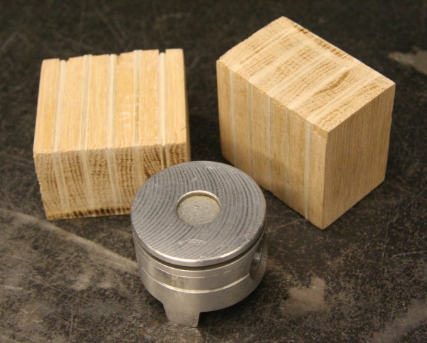
This brings me to today’s blog posting. I’m starting of slow just to get things rolling. I did a project for a friend of mine that involved a custom shifter knob, which he designed, for his 911 Porsche. He wanted something unique yet vintage looking for his 1973 SC. He had taken apart an old R12 air conditioning compressor from a different 911 and salvaged the pistons out of it. They are a perfect size to build a shift knob from.
Instead of just plunking a piston down on top of the shift rod he figured a nice wood accent would lend itself well to a retro look. After we tossed some ideas around he/we settled on the following. I think it all worked out to his liking and should he wish to covert back to stock I didn’t modify anything on the vehicle side that would prevent him from doing so. Like the good ole days I’ll let the pictures do the talking.
This is my friend Jon’s Moss Green Metallic 1981 911 SC ROW/German spec’d Porsche that is getting the shift knob retrofit.
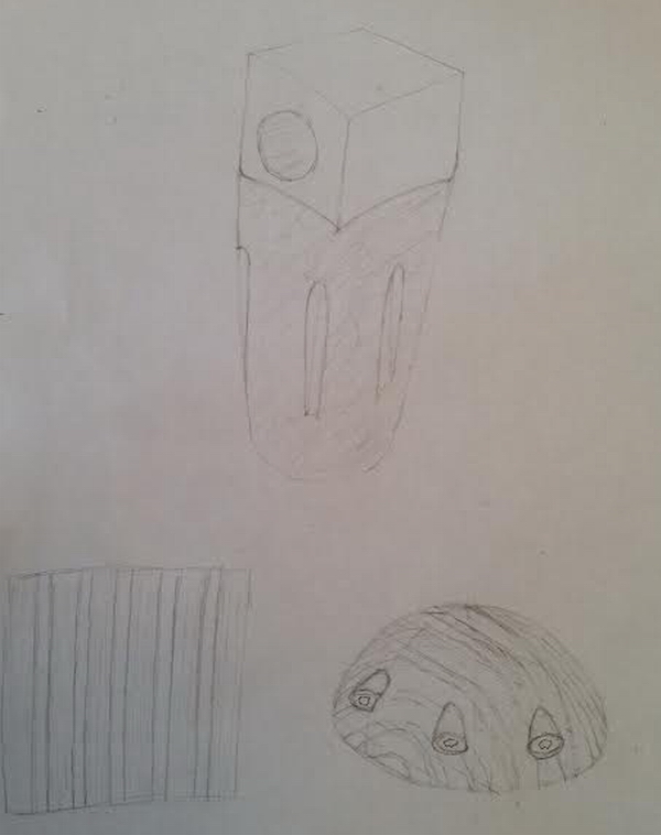
This is the Mad (Manual-aided design) that my friend provided to me as the official concept design and blueprint. He can draw better than I can.
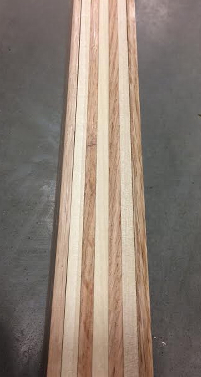
We played with different woods, and wood patterns, every time one of us was out at a store that carried project wood. This is 1/4″ maple and oak stacked as a sample.
The wood, and pattern, that was settled upon was 1/8″ birch plywood sandwiched with 1/4″ solid oak.
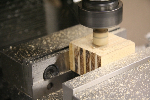
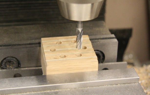
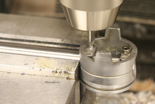
My friend supplied me the wood already glued and in blocks (yes plural, always have a back up plan). First order of business is to mill a flat surface to work from using a router bit chucked up in the mill.
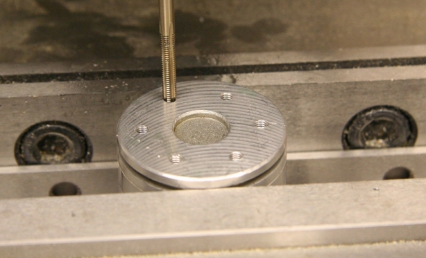
The wood was then drilled out in order to accept 4mm socket head stainless steel bolts. I use an end mill in order to counter sink the socket heads.
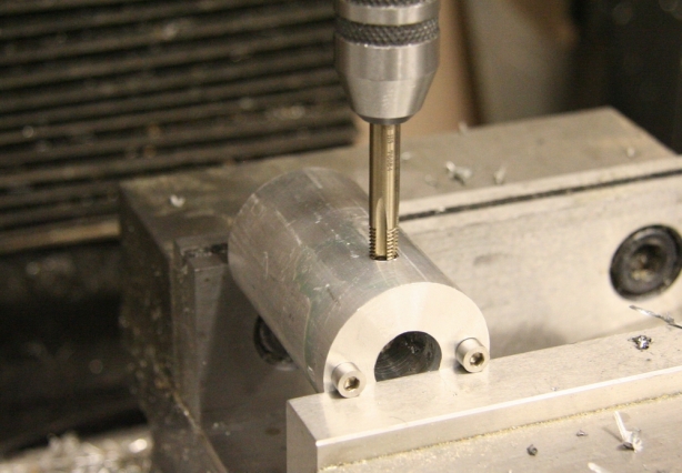
Next the piston was drilled and 4mm tapped in the same pattern.
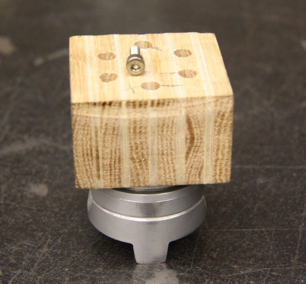
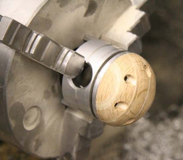
The prepped blank and piston get hitched and are ready to go for a spin.
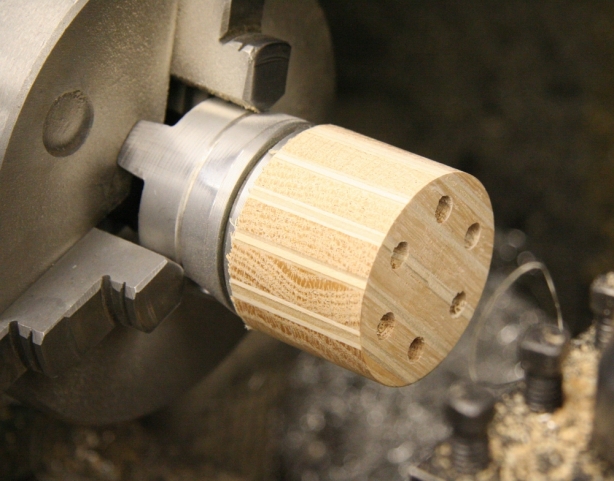
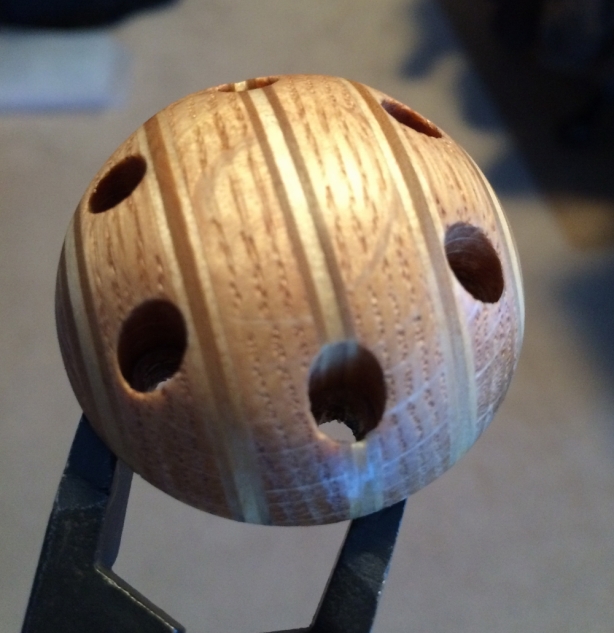
The diameter was roughed down to size using a carbide cutter on the lathe.
The profile was also roughed out using a carbide tip to where the shape was close. The fine dimensions where then cleaned up using sandpaper.
With the top rough fabricated it was time to direct the attention to the base. The piston required some kind of mounting to the shifter rod. The understand of the piston was drilled on the pin bosses.
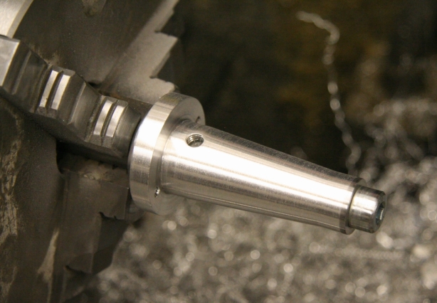
Using some 6061 aluminum stock the end was faced and drilled to the same dimensions as the underside of the piston. The radius side was then drilled and tapped in order to accept a set screw which will secure the sleeve to the factory shift rod.
Moved onto the lathe to start shaving material off and bring the profile to a clean, light, shape.
Onto the finishing stage. The piston top received a couple of coats of a polyurethane clear coat to aid in protection, It will hopefully help add some “character” wear as the piston gets some use.
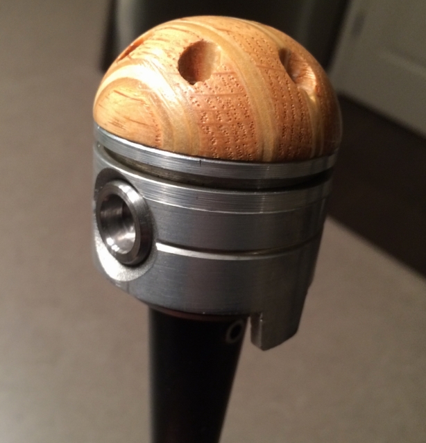
This is the assembled piston. This photo shows some details that I didn’t cover in the previous build pictures. Mainly the fake wrist pins. The one pin you can see is actually a “nut” that allows the fabbed sleeve to bolt to the piston. The sleeve, which is blurred out, received a shot of primer and the was airbrushed black.
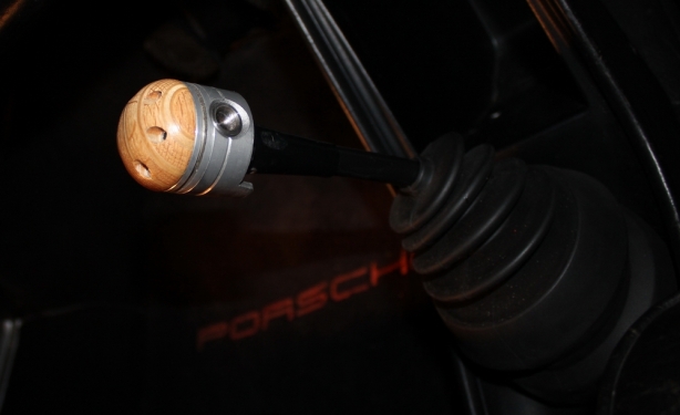
Installed and ready to synchronize some constant mesh
As with many of my garage projects this next one started with someone else’s idea. A good friend of mine decided to get himself self educated in luthiering. For those of you who do not know what a luthier is Wikipedia defines it as someone who makes or repairs string instruments generally consisting of a neck and a sound box. It is better known as a guitar builder. He plays guitar and had the urge, and the skills, to be able to build his own electric 6 string.
He had already started his build before he approached me with his idea. He works much the same way as I do in respects to how he stages his builds. Although he had his current project well under way he was already thinking ahead to his second guitar build. For his current build he opted to purchase a pre-fabbed neck. For his next guitar he was planning to custom build the neck from scratch and this is the point where I enter in.
He required a way to cut the fret slots into the neck. Basically he need a high precision miter box in order to mount the neck blank square and then miter a slot to a precise depth using a fret saw. These fret miter boxes are nothing new as there are companies that exist who sell miter boxes specifically for this purpose. He approached me thinking that I may be able to come up with a custom design that would suit his needs.
So one early Saturday morning we met for breakfast and blueprinted out a rough design. Threw some ideas around and I was able to get a solid idea of what he needed the box to do. Best part was that as long as it accomplished the required task I was free to build it anyway I wanted to. I love not being constricted by boundaries. I had planned to combine materials in order to make the visuals worth looking at. I opted to use brass, oak, and aluminum in order to give it a unique image. Guitar building is precise, requires patience, and needs a deep philosophical understanding of craftsmanship therefore the tools that are used to build the guitar should meet the same standards as the luthier possesses. So, like usual, the following pictures take you through the entire build.
I planned to sandwich the fret saw blade in between 8 sealed ball bearings. I acquired high precision ball bearings used for router bits. The bearings will all get supported by brass spacers. I acquired a small Taig lathe awhile back which works great for small, precision, parts so I spun all the brass spacers out using it.
This is the ball bearing set up that will eventually get installed into 4 main aluminum supports.
Time to get the main vertical supports fabricated. Started off with some 6061 aluminum and squared it all up in the mill.
Milling out slots that will accept the ball bearing assemblies.
The miter box will require adjustment to accommodate fret saw blade thickness. 2 of the vertical supports were slotted to allow for adjustment.
Cross drilling and tapping holes to allow for a set screw to be threaded in and therefore secure the ball bearing assemblies. The hole will be hidden on the bottom thereby making the top, visual, portion of the support super clean.
I needed to secure different widths of the fret board blank into the base of the miter box. I came up with a cam system that would adjust to widths. Here I am spinning out one of the brass cams. Keep scrolling as more pictures will show exactly how this cam works.
The 2 brass cams required clearance in order to spin and adjust therefore the 2 rear vertical supports got milled in order to allow for cam clearance.
Time to lighten things up and shave off some excess material. The vertical supports didn’t require all the aluminum they started off with so I shave some off just to give them better visuals.
Since I was on a roll I thought I would try and prevent things from getting too mundane so I opted to drop a ball nose endmill into the supports to give them a good visual dimension.
Onto building some feet. They were machined from some round stock aluminum and then milled out to mount flush with the oak base.
Drilled and chamferred to accept stainless steel hardware.
Moving onto the depth stop for the saw blade. This will all make sense later. I machined some brass guide pins on the Taig lathe. I built a radius turner for the lather in order to get I beautiful contour finish.
More depth stop milling.
Time for another mill clean up.
With most of the aluminum machining completed I moved onto the oak base. I used a combination of endmills and router bits in the mill. Although the mill can’t even come close to putting out the RPM a router does it still does the job well. Here I drill all the holes in order to mount the brass and aluminum to.
I hate screwing into wood as it feels so imprecise to me. All the drilled holes received 1/4″ thread steel inserts therefore implementing metal threads.
Taking the edge of the base using a radius router bit on the mill.
And here are all the fabricated components that will eventually make up the miter box. Seem a bit excessive considering the tool only has to cut 1 slot.
The bearing assemblies get secured using hidden set screws.
These are all the components that make up the blade depth stop.
And these are all components assembled that make up the blade depth stop.
Before I go into finishing stage I mock everything up to ensure that it all works the way my brain designed it to.
The box gets disassembled and then the finishing process begins. The oak base received a couple coats of stain.
I thought since the miter box was a one-off design I would customize specifically to my friend. His name is Fabrizio and so I came up with an unapproved logo for him. I cut out a stencil on my vinyl plotter so that I could embed the logo into the oak base.
Using my airbrush I experimented with some colors on some scrap. I came up with a trio combination of colors that would suit the overall appearance of the design.
Applied the stencil, taped of the remainder, and started laying down the paint.
Once the logo was airbrushed in the oak received a polyurethane clear coat finish in order to protect both the logo and the work surface.
All the aluminum received hand brushing using a 320 grit paper.
Since the miter box required adjustment before use I built in a spring loaded hex key holder. A couple plungers and springs would allow for tool storage in the base.
This is a shot of me drilling only 2 holes for my friend in his original electric 6 string build. I want to be very clear here that I had NOTHING to do with his build. It was all him and all I simply did was drill 2 precision holes for him. His progress looks fantastic.
So here I move onto the pictures showing the completed build. You can get an idea of how everything works from this shot. The saw gets sandwiched between the bearing assemblies and then the top brass support of the saw is what contacts the depth stop.
Here one of the brass cams are evident. The 1/4″ stainless steel Allen head bolt gets loosened and then the cam can be pivoted and locked into place to allow for different neck widths.
The 2 spring loaded hex key holders are shown here. All that is required is light push in of the key and then a 90 degree turn in order to release it from the base.
Close up shot of the bearing assemblies.
This is the depth stop mounted to the verticals.
Here the 2 brass guide pins are visible. The center screw is used for precision adjustment of the depth height. I installed a rubber protective cap on the end of the adjustment screw in order to prevent any damage to the guitar neck due to contact with sharp edges.
I won’t go into great detail about how the depth stop set up is done however I will mention this. The stop can be precisely set using feeler blades. The saw in inserted and rested on top of the require feeler blades which represent the required depth. The depth stop is then locked into place.
You can see the slotted screw in the center and on top which is what is used to adjust the depth stop vertically. The stop is then locked into place using 2 set screws (shown being tightened) that lock into the brass guide pins.
The screw that is being pointed out allows for adjustment to accommodate different saw blade thicknesses. If only 1 saw is ever being used there is no reason to have to ever need to adjust this after the initial setting has been made. There are a total of 4 adjustment screws.
Here shows the adjustment and lock down of the brass neck width cams.
The underside of the miter box shows the aluminum supports. I built the 2 end feet with holes to accommodate screws in order to secure the box to a work bench. The center aluminum “GG” logo plate is simply there to provide support and prevent the oak from bowing.
For those interested this is the fret saw that is being used for the build.
This post wouldn’t be complete without showcasing Fabrizio’s first guitar build. The lines and zebra finish are fantastic! At this point the guitar is only mocked up which is evident by missing hardware. Photo credit goes to Fabrizio Tessaro.
And as an added bonus we all get to enjoy a 30 second riff featuring Fabrizio rippn’ on his custom in gordsgarage. NOTE: Do not judge the quality, the session was impromptu and features sound courtesy of a low end practice amplifier with absolutely no consideration given to sound set up.
This blog entry is a bit out of the ordinary however it still involves the garage and building things. Today’s project involves a mission I have been on for almost a year and a half and it involves introducing the love I have for metal, building, and mechanical things, into other parts of my life. As the title suggests it was a lesson that came at a price however that is of little concern to me. It was a project worth completing.
It all started with the exposure to the unlimited amount of “body” products, and soaps, designed, and available, for women. It’s endless! I personally do not have a desire to have the same products available to me however I thought that if something was available that was to my liking I would potentially appreciate it. There is always a small line of men’s soap products available but it is limited plus I would never take the time to actually purchase it.
So like I said I wouldn’t take the time however I have no problem spending countless hours designing and making my own soap that I would consider worthy of being used. And so this brings us to the current blog posting. Soap making 101 gordsgarage style.
Of course with any project there is always research and planning involved. Since I had no idea how to make soap from scratch I decided that would be a good place to start. Flipping through the course catalog advertising adult weekend classes I found the course I needed which would teach me the basic skills of soap making. Turned out this class is not all that popular with the guys as I was the only one. Didn’t matter to me, I was on a mission and had a bigger plan then just leaving a class with a few bars of scented soap in the shape of flowers.
So the training course was very good and in approximately 6 hours I had a decent understanding of the process, equipment, and supplies required to turn out all natural soap. I tooled up and made a few batches at home to ensure I could produce a decent result on my own. No problem. Now it was time to put the project into motion. The plan was to turn out handmade, all natural, gear shaped soap made to look like machined metal.
I admit this is not the usual type of garage project I share mostly because it doesn’t actually involve metal however it does involve the garage, fabrication, R&D, and most importantly the learning of a new skill. I’ll let the pictures tell the story.
The start of the gear soap required coming up with a blank that I could create a soap mold from. I had created a 2D model of what I wanted and then got in touch with my friend Jason over at The Gahooa Perspective. Jason just happens to have a very nicely equipped shop which includes a CAMaster CNC router table. Jason had agreed to help me out by routering out a blank from some High Density Polyethylene. The photo is a screen shot from the CAM program used to generate the G-code for the CNC.
Jason managed to cut a couple of samples for me. They worked out fantastic, the cut quality was perfect for molding.
The following video shows the CNC table set up Jason has in his shop. The CAMaster Cobra is a work horse of a machine and is fascinating to watch. I would highly recommend you all visit Jason’s blog, The Gahooa Perspective, to check out his cool projects.
So here are the mold blanks. 2 of them Jason cut out of HDPE and the 3rd one (blue) was done on a 3D printer by a friend of his. The 3D printed one had fairly precise lines however the finish, to make a mold from, was not as good as the CNC routered ones.
So now comes my time to put some effort into the project. I need to create silicone molds of the gear and therefore need someway to house the blank in order to pour silicone. I decided to build a housing out of a toilet flange since it was cheap, easy to machine, water proof, and had a great finish to release the mold from. The flange required some clean up on the lathe prior to building the rest of the housing.
I required a method of securing the gear into the center of my mold housing. On the back side of the gear I drilled and installed a metal 1/4 x 20 threaded insert.
Here is my completed mold housing. It is fairly simple. The gear and the flange both get bolted onto the base plate. The only change I made that is not shown in this picture is that I applied some white vinyl to the steel backing plate in order to allow for clean release of the silicone.
And here we go for the first run of mold making 101. I have never done it so I am not completely sure what to expect. I am using Mold Star 16 Fast which is a 2 part silicone that sets up in approximately 30 minutes.
Ready to go! I am doing this in the house since the silicone is fairly temperature sensitive to ensure proper set up. The garage is just a bit on the cooler side.
Mixed up and pouring. In 30 minutes I unbolt the housing and remove the mold.
Tick Tock
I spray the mold with a mold release prior to pouring. This is a shot of the base plate removed. Everything slides apart nicely.
This is a completed mold. The detail is fantastic! I made sure to build the mold walls thick enough the ensure good support of the liquid soap.
Although this is only a single picture in a blog posting of 30+ shots it represents where most of my time on the project was spent. What you are looking at is a run of soap in its natural color. I performed many test batches of soap to ensure I would be able to get the detail from the mold into the soap. I struggled, a lot. Although I could achieve good results in the teeth and body of the soap I could never get the “GG” and “bolt holes” to consistently release from the mold and produce good consistent results.
Here is the result of many failed attempts at building “GG” soap. I felt after performing multiple different techniques to get the soap to release properly I hade no choice but modify the design. It pained me to chuck up the blank in the lathe a machine off the face of the gear. My deepest apologies Jason, if there was any other way to solve the issue I wouldn’t have cut up your work.
And here you can see the result of what 5 minutes on the lathe turned out. No more “GG”
Back to running new molds. I had previously made 3 molds of the “GG” design. This time I am going all in and doing a run of 7 molds feeling fairly confident that this design will work.
And here is the new, simpler, design.
So now a word, or 2, about the actual soap. Since this is “garage” soap it is being made in the garage all from raw ingredients. I use a basic soap recipe that produces a good cleaning, scentless, and lathering, soap. Because this is gordsgarage soap I felt it was appropriate to add my own signature to it. I wanted something that you wouldn’t be able to find in someone else’s soap and wanted it to be distinguished from others therefore making it truly garage soap. Although cleaning your body with engine oil and cutting fluid would be considered unhealthy I opt to put 1 drop of Relton cutting fluid and 1 drop of Mobil 1 engine oil into every batch of soap I make. This way when you are singing in the shower you can feel connected to that part of your life that brings you so much joy. A batch of soap produces 7 gears and therefore 2 drops of oil is hardly enough to cause any issues. I have been way more exposed to the stuff just working in the garage.
It was also time to start adding the color to my soap. My initial plan was to find a color combination that would look like freshly machined 6061 aluminum. This was harder then I expected. I ordered up some powered mica in various colors that would allow me to experiment with colors. Here I weighed out some Polished Silver for a base color and then some Pearl Basics to give it some sparkle. It’ll take many batches before I find the color I like.
With all my fats and oils weighed out it was time to add the drop of cutting fluid and engine oil. I should probably mention that I’m not going to cover the actual soap making process, there are a bazillion websites out there that already cover this and I probably couldn’t do it any better.
With everything, but the lye, added into the pot it was time to start heating things up. I use the same hotplate for soap making as I do for anodizing.
With everything brought to within 100 degrees Fahrenheit it was time to bring it all together and start mixing. The lye gets added to my fat/oil solution, mixed, and then my color is introduced.
Soap is then poured into 7 molds and allowed to set up for 24 hours.
Once the 24 hours have passed, after pouring the soap, the gears get removed from the molds and then set aside for 30 days to allow for the saponification process to occur. After 30 days the soap firms up and is ready for use.
Here is an example of where R&D went wrong. In my quest to find some aluminum looking mica to dye the soap with I had ordered some mica that actually contained aluminum in it. As I know from my anodizing experiences that lye (caustic soda) and aluminum do not get along. There are always warnings that you are not to clean aluminum with caustic soda. I use it on aluminum to remove anodizing simply because it eats into the aluminum. In the case of my soap making the aluminum mica reacted with my lye solution and turned my soap into a huge foaming failure. Took me awhile to clean all the molds out. Lesson learned.
So with the soap making under control I figured the finished product should get some packaging. This is were I get my brother, Brian, involved as he it the guy you want to know when it comes to graphic design. I asked for his help to get a label design built. Between the two of use we were able to come up with the following.
This is the computer generated sample of the soap label. This is what I will be supplying to the label manufacturer to have printed up on 2.250″ circular vinyl.
I sent the file off to the printers and in a couple weeks I had myself some professional looking labels.
With the label created and printed I needed to come up with a protective packaging material. Initially I had wanted to use brown paper tool wrap with wax paper on one side. This stuff is known as VCI Paper (Vapour Corrosion Inhibitor). I think it looks totally old school and would suit the project well. The down side is that it hides the beauty of the gear shape. I settled on using a heat shrink type of plastic that snugs up around the soap using a heat gun. This way the soap is protected yet still visible.
So with most of the hurdles hurdled it was time to start cranking out production. Still not sure what color I will officially settle on. I continue to make each batch different. I think I am liking the darker ones more and more.
Today’s posting comes as part 2, of 2, which outlines the restoration of a 1907 Champion Blower and Forge Co post drill press for my cities local living history museum. If you happen to miss part one there is no need to get all worked up. You can view it here.
Previously all the repair work and fabrication had been completed. It was time to move onto the finishing stage. There is not a whole lot that is worth putting into words as I have jam packed this blog posting with a lot of pictures.
In an effort to avoid redundancy I will simple start this posting with some closing remarks. The end product worked out as planned and I am happy with it. For me the absolute best part of the restoration is how well the post drill operates. If there was some way I could get all those interested to turn the handle and experience the ease, and smoothness, of the drill that would tickle me more than anything I’ve seen. Unfortunately you are going to have to take my word for it. I think as far as looks go it appears to have come from the era. Although I made some “non-period correct” changes the bulk of the drill remained original.
I have since returned the post back to its original home that I received it from. The plan is that its use will get demonstrated to the people visiting the facility. Since the drill is now kept in an indoor shop it should stay in good operating condition for many years. It was an enjoyable project of mine and I was happy to have it all work out in the end. Time to move onto something else. Below are all the pictures that follow the completion of the post drill. And BTW…virtual high five to those who decipher the title to this post.
I entered into deliberation regarding the highlighting of the raised lettering. Before I went into finishing stage I thought I would sample the highlight. I used a dark copper model paint and a artists paint brush to raise out the lettering. Still completely unsure if this would be too much. Hmmmm…….
All the components receiving a black top coat were wiped down with acetone and then oil & grease remover. I opted to not set up my paint booth as I was not overly concerned with some dust getting into the finish. All the components then received a coat of Nason primer.
I originally wanted to powder coat everything but it became clear, awhile back, that it would look too “plastic” so I went for conventional paint. I dug out my HVLP spray gun and figured I would Hot Rod black the components. This is the same paint I used on my 1965 Honda CB160 Cafe Racer. It has a decent flat finish to it.
Paint is mixed, filtered, and ready to spray!
Painting results were great, no runs and no missed spots. My intention was to paint the gear teeth and allow them to wear naturally.
I was struggling a bit with the hardware. The drill press came with mismatched square head set screws. I couldn’t cope with that. I found myself on the West Coast of Vancouver for a couple of days and decided to stop in at my favorite hardware store located in Steveston. This place is fantastic! I could spend hours just wandering the isles.
And wander the isles I did! I was able to find the retro square headed set screws that I needed. Score!
All the hardware received and initial cleaning.
Next step everything took its turn in the crushed glass media cabinet and received an exfoliation.
Then onto the black oxide solution where everything got blackened to the same degree.
Once blackened all the hardware received a coat of sealer in order to protect it from rusting.
Hung to dry. I feel better having the finish of all the hardware matching.
The 2 oak handles that I made received a couple coats of stain and then 2 coats of a clear polyurethane finish to aid in the protection.
The next sequence of pictures revolve around saving the drill table from any more damage. At some point in the drills earlier life the drill table was drilled into. In my previous post I showed I repaired the previous holes. I didn’t want the repaired table to get drilled into again so I decided to make a “sacrificial” table hoping it would take the abuse and not the original table. It started off with plasma cutting a 7 inch diameter circle out of some 10 gauge steel.
Onto the milling machine where the center was drilled out as well as 3 more holes spaced 120 degrees apart.
Quickly machined up a center arbor for the 7″ disc.
TIG welded the center arbor to the disc which will allow me to mount the disc into my lather chuck.
With the plasma cut circle mounted in the lathe I was able to trim it down to a precise diameter.
Time to move onto the actual sacrificial plate. I got my hands on a chunk of 8″ wide by 1″ thick solid red oak. I jig sawed out a rough 7 inch circle.
Next is was mounted onto my previously machined 10 gauge steel disc using wood screws.
And onto the lathe it went.
It was trimmed down, and sanded, to final dimensions.
Three 1/4 x 20 steel inserts where installed.
2 coats of stain and 2 coats of a clear polyurethane finish were applied to give it some protection.
I machined up 3 brass pegs to allow for mounting the oak base to the powder coated steel base. This way the sacrificial base can be dropped onto the original drill press base quickly. I also designed it that if the 1″ oak gets drilled all the way through the bit will eventually hit the steel backing. If the operator chooses to continue drilling through the steel base into the drill table then I suggest he/she steps away from the machine and never gets within 10 feet of it again.
Here I am back onto my highlight dilemma. I applied some more of the dark copper model paint to the back side of a flat black mount. I think at this point I am going to decline from highlighting the raised lettering. As cool as I think it would look I need to ensure that post drill looks period correct. Back in the day the manufacturer would not take the time to apply the highlights.
This is most of the hardware that has been cleaned up, refinished, or replaced.
What holds the drill arbor to the down feed acme rod is a couple of 3/16″ pins. Originally there was a “one time use” crush sleeve that went over the pins in order to prevent them from coming out. I opted to machine a bronze sleeve with a set screw to allow for servicing. As stated in my previous post I am aware that this repair is not period correct.
A friend of mine stopped by the garage for a visit so we figured we would have some fun with the assembly of the post drill. If you would like to see all components involved as well as the construction take a peek at the following 58 second video.
Thought I would include a photo of the wood shop that the post drill will live in. This place is super cool! It is run by volunteers and what they turn out of the shop is magical. Right now they are building a carousel for the local zoo. The ride is going to feature all hand carved animals done by the volunteers. I have no idea how they pull this stuff off. It is a pleasure to see the passion these people have for working with their hands.
The remaining 14 pictures and 1 video are not being accompanied with any captions. They are simple showing the different angles, components, and details of the post drill. As much as I do not want to overdo the pictures I like to provide as much visual detail as possible in hopes that anyone else that is looking for information regarding these presses will be able to find some answers here.
My latest garage project is coming to me through a series of connections and it involves a restoration project. My cities living history museum has an on-site workshop that is run by volunteers. The workshop is historic type wood working shop that does lots of repairs and building of historic items for the museum/park. One of the larger projects undertaken by the shop has been a full blown building of a 1920 carousel including all hand carved horses.
Doug, the gentleman that heads up all the volunteers and also appears to coordinate practically everything to do with the projects, gave me an inside look at both the shop and some of the major projects that have been completed. The vintage level that the shop works on is truly inspiring and goes to show that machines can’t always substitute for human talent, effort, and ingenuity.
This brings me to my own little shop and the project it has recently seen. The historical park has many vintage pieces of equipment some of which has been donated. They had acquired a Champion Blower and Forge Co. drill press dated from the early 1900’s. The drill had found itself a home in the wood working shop but was only there for decoration as it was not in a useable state. Through a series of connections I was able to contact Doug and meet with him to discuss the future of the drill press.
What the museum wanted was to be able to get the drill to a functioning state so that it could be used as demonstration in the museum’s workshop. After performing my initial inspection I was fairly certain I could get the drill back to working condition again however I had one main concern. The concern revolved around restoring it so that it would be historically correct. I like building things, I like spending time in my shop, I like planning my projects, and I like researching my projects BUT…I do not want to commit to the amount of time it would take to research the historical accuracies nor do I want to be burdened with the time consuming task of trying to collect potentially unobtainable items. Since this is a volunteer venture I also have to consider the budget. It was agreed that the drill would not have to be historically correct. As long as it was in a functioning state and that the overall image was maintained then I was free to modify, and repair, as I see fit.
The good news is that I wasn’t under a time crunch. The museum, being mostly outdoors, shuts down for the winter therefore I had up to 5 months to get the project complete. As long as the drill was ready for opening day in May I was free to take my time.
Onto the details. The Champion Blower and Forge Co. drill press that I am dealing with is Model 101. I found a date stamp on the drill chuck and it read June 1907. I am not going to give a history lesson in this blog posting. I will refer you to Mr. Google should you have any questions. I will, however, tell you a bit about how it operates.
The drill press is hand cranked and only has one gear ratio. The length of the crank arm can be adjusted and therefore I guess you could say that the mechanical advantage can be altered. The unit is equipped with a flywheel in order to add some inertia to the monotonous cranking of the handle. There is a cam lobe cast into the drive gear which activates a cam lever which, in turn, ratchets a lever onto a downfeed gear. This allows the drill bit to feed down between 1-3 teeth, depending on adjustment, with every turn of the crank arm. I have included a video in this post which will probably do a better job at explaining how the unit operates.
There is much that I can say about both the drill and the restoration process. All the components had been gone through and either repaired or reconditioned. Some small hardware items like screws, ball bearings, and a spring were replaced. I have not included all the details of the repairs in the posting but instead just chose to highlight a few. If you have questions or want specific information just ask!
On last note before I move onto the good stuff. Much of the hardware that I required for the build was hard to find locally. McMaster Carr is a United States hardware supplier that has a massive selection of parts that are of interest to me. Unfortunately McMaster Carr does not sell, nor ship, to Canadians. Fortunately I have some good friends in the right spots that are willing to help out. Jason who happens to follow my blog was able to help me out. For those of you who are not familiar with Jason I would highly recommend checking out his blog as he does some really cool wood related projects. Not to mention he is an equipment junky which I can respect. You can see all his stuff at his blog The Gahooa Perspective. Anyway, Jason offered to put an order in for me and ship it North my way. Very much appreciated Jason, thanks!
I opted to split this project into 2 separate posts. This post includes the nitty gritty parts of the restoration. Part 2 will include the finishing process which will be available at a later date.
Here is the condition of the drill press before any work was performed. Previous work had been done as was evident by weld repairs that were painted over.
I am including this shot only to show the right side for reference purposes. As I scoured the internet in my research it was helpful when I was able to view as much detail as possible. Here is my contribution.
First order of business was to photograph everything before disassembly. Second order of business to to rip and tear and break everything down to individual components to allow for cleaning and inspection. Most of the components came apart with little effort. There where a few parts that needed some persuading however I think the drill and I developed a good working relationship. It had initially expressed some dislike of what I was trying to do but I had assured it, as gracefully as I could, that I was here to help and not to harm. We were able to reach a compromise and at that point I think we each developed a healthly respect for one another. From then one we had a common goal and became good working partners. I would like to be able to call this press a friend.
Here is some evidence of previous repairs. The support that holds the table assembly has been previously broken into multiple pieces. As much as the brazing repair looks excessive I commend whoever performed to repair for a job fairly well done. If you saw the bore of the broken component you would know just how many pieces it was broken into. It was a jigsaw puzzle to repair.
This is the cam arm that converts movement from a vertical plane to a horizontal plane which then activates the down feed ratchet gear. It too has been previously broken and repaired with both brazing and welding. There were some cracks that were still evident so I will end up doing further stitching.
Once I evaluated the condition of all the items I proceeded to get everything to a workable state. I started by running everything through a high pressure hot water parts cleaner to get rid of as much grease, oil, and old paint as possible. Then most components were transferred to my blast cabinet and cleaned up using crushed glass media.
The drill press table had been previously drilled through. Being cast I was nervous about how I was going to repair this. I had TIG welded cast previously and had good success. My main concern was being able to match the material finish.
I filled the holes using a 309 filler rod which works great for dissimilar metals. You can see that cracking on the top of the weld is evident. I am hoping that crack is only a flesh wound and has not penetrated deeper.
I had knocked down the protruding portion of the weld and then set the table up on the mill in order to machine it using my facing mill.
Here is the end result after machining and some sanding. The table is perfectly flat however the repair is evident, I kinda expected it would be. I am not sure how I am going to deal with this yet, I have some ideas. Time will tell which solution will prevail.
The drill press had a previous repair done to the wooden handle on the crank arm. I felt as though the press deserved something more then low budget fir. I opted to machine out a couple of oak handles using classic handle styling by giving them a slight taper.
Roughed out and sanded oak handle.
You may have noticed that the drill press only had 1 handle originally and that I had machined 2 handles. This is because I opted to retro fit an upper handle onto the top down feed gear. Of the drill press models that I researched I saw numerous models equipped with this upper handle. The purpose of the handle was to aid in rapid vertical feed of the drill chuck when setting up the material for drilling. The 101 model I was dealing will had a hole in the casting of the the upper gear that allowed for a handle to be added. I am unsure if a handle was there as some point or if it did not come on this model. The provisions were there so I opted to add my own handle assembly. I wanted to keep all my “gordsgarage” manufactured components looking as though they were original so I built a simple arbor for the upper handle. This is the start of the arbor before the final machining took place.
Here is the final machined upper handle arbor. I needed to cut it in such a way that it would clear the down feed ratchet lever.
One of the more crucial repairs involved the drive gear . This is the gear that is turned directly by the crank handle. The problem was that the gear had worn on the shaft and therefore the teeth would no longer mesh due to misalignment. The gear is cast with no inner bushing. Since the shaft that it rides on inspected to have some wear it was fairly minor. I opted to enlarge the bore of the gear in order to accept a bronze bushing.
Here is the bronze bushing that I machined down in order to fit the gear and the shaft.
The bronze bushing then got press fit into the gear. I made the bronze bushing a very tight fit on the shaft knowing that once it was pressed into the gear I would be able to hone the bushing for a precision fit. Happy to say my gear teeth meshing issue was solved and the gear alignments were perfect.
The next few pictures show some random repairs. On the right is shown the cam wheel that rides on the drive gear and activates the cam arm. There were a couple issues with it. First it had a flat spot on one side most likely caused by it’s inability to turn freely. The second issue was that the securing screw, for the wheel, could not be tightened since it would not allow the wheel to turn. What the manufacturer did was thread the screw in loose and then mushroom the back side of the treads in order to lock it in place. The problem using this method of securing is that it does not allow for disassembly for maintenance or repair. My solution involved machining a new wheel that was equipped with an inner bushing for the wheel to rotate around. This way the allen head securing bolt can be tightened properly and also removed at a later date if needed to. NOTE: I realize the allen bolt I used is not period correct. Fortunately the drive gear blocks it from sight.
Next challenge was to address a one-time-use crush sleeve. The sleeve on the right was used to keep a couple of securing pins in place. The securing pins connected the drill chuck shaft to the down feed acme shaft. One-time-use is the issue and unfortunately for me I was second in line. I wanted to find a solution that would not only look similar to OEM equipment but also allow for disassembly. I machined a bronze sleeve and installed a 10-24 set screw. I opted to leave the outside of the sleeve untouched therefore keeping its worn looking exterior. Again I realize the set screw does not fit with the time period. It’s my project and I can screw with it if I want to. That’s just my one cents.
Just like the cam wheel the cam lever also needed to be able to turn/pivot on it’s securing fastener. The cam lever pivot was originally made from a 7/16 bolt shown on the right. If this bolt was tightend it would not allow the lever to pivot. In order to keep the bolt “loose” but prevent it from backing off the threads have been flattened. This is visible by looking at the deformed thread 6 threads from the end of the bolt on the right. I am not huge supporter in this securing technique and therefore a solution would be required. The second issue was that the female threads that were cut into the lever arm securing bracket were cut at a slight angle. This caused issues with proper lever alignment. My solution invloved building what is visible on the left. It is a bushing that is secured using a 3/8″ square headed (keep the vintage look) bolt. Not only did this allow me to tighten the bolt, it also allowed a better quality pivot, and it repaired 90% of my lever alignment issues due to the fact I eliminated using the angle threaded original hole. Got all that? Didn’t think so.
Another challenge involved the down feed 5/8″ six turn single start acme rod. The drill appeared to have sat for awhile in unfavorable envirmental conditions a therefore the threads suffered some corrosion. I opted not to reuse the orignal shaft but instead build a new one. I began by obtaining a new three foot section of 5/8″ acme rod, cutting it down to size, building up a portion of it with the TIG welder and a 309 rod, and then machining it down to match the spec of the original rod.
In this picture the corrosion of the original threads are evident on the bottom shaft. I am happy to say that the female threads were still is decent condition and that the new, replacement, shaft threads perfectly into its counterpart.
Below is a 32 second video showing the mocked up drill press in action. Normally I toss in some generic music to help pass the video viewing time but in this case I opted not to. The reason being that the pure mechanical sound that this drill press makes is symphonic. I almost think the mechanical sound of the unit working in harmony is the best part. I’m considering making a 3 minute recording and put it up for sale on iTunes. Coming home after a hard days work , sitting in your Lazy Boy with a set of headphones on, and entering an oasis of non cyber stimulation would be well deserved for those in appreciation of such mechanical bliss.
The last 2 pictures show the mock up stage. Do not look too hard at the assembly since I purposely did not assembly everything 100%. The securing pins below the bearing assembly are just loosely fitted in order to allow for easy disassembly. At this point though the fabrication and repair have all bee completed and I am happy to say that the drill performd very well. I have never had the opportunity to use on of these drills in it’s original state so I can’t comment if my rendition if better, worse, or the same however I would have no hesitation in guaranteeing all the work I performed.
At this point the drill will be completely dissembled and the “finishing” process will begin. I’ll save all those details and pictures for a later date.
Often I run impromptu sessions in the garage. These times are usually highly satisfying for me as they usually occur when I have just cleaned the shop, everything is organized, and I have available to me the equipment and supplies. Often I spend the time, when I should be sleeping, laying awake brain CADing the next project. The spontaneous projects are great because I just start to wing it and make whatever I have work.
I have a couple of friends that work at the local Audi and Hyundai dealerships in town. The Audi friend is a service manager and the Hyundai friend is a partsman. I figured their desks may benefit from a customized, one off, business card holder.
I scrounged around the shop looking for automotive related parts that I have stashed in various corners. I collected a few components that would lend themselves well to some modifying and decided to build some unique card holders. Below are the pictures showing what I came up with off the top of my head.
Sorry, no shots of the milling of the piston top. The first card holder consisted of a old BMW piston and an aftermarket rear spring lowering perch for a mk4 VW. The piston top was milled to fit business cards and then both the perch and piston were polished.
The polished piston top was taped off and the bottom half was the glass media blasted.
The Glacier White powder coating was fogged on and the assembly was baked.
I plotted out Hyundai decals on some gloss black vinyl to add to the customized look.
Done deal! Quick and easy.
As you may know I am I big fan of retro and vintage styling. I keep the polishing down to a “not so gleaming” level as I think it looks better.
The spring perch height was a little too tall so trimmed it down a bit. The base was cut on the lather in order to ensure it would press fit into the piston base. The jam nuts were left untouched.
I think the style suits a parts persons desk.
My next card holder took a little more machining. It started out with a rod of 6061 aluminum. I offset it in the lather chuck and drilled an off center hole straight through. I have a four jaw chuck that allows me to offset the stock properly however in this case I was lazy and the precision was not required so I opted to just toss a spacer into the 3 jaw. It works.
Onto the mill where I used a ball nosed end mill to cut some slots through the narrow side.
Next I moved onto a section of 1.000″ 6061 solid square bar where I dropped an end mill part way through it.
Next I hogged out a section where the business cards would slide through.
Onto the band saw where the milled bar was trimmed to length using a 45 degree angle.
All the components would get bolted together so I drilled, and countersunk, the hole for the stainless steel fastener.
Here are all the components that make up the card holder. The large valve is from an air cooled Porsche 911 and the the small valve was from my Honda CB160 cafe racer.
The aluminum components received a brushed finish. I like it!
Both valves received a polishing.
An Audi rings decal was plotted and applied. Done deal!
The small valve was secured with a set screw. The large valve was press fit into the aluminum rod and the secured using the stainless steel socket head cap screw.
One day I had an idea, went into the garage and built it. The End.
Not sure what more I can say about this post. I thought it would be cool to make more of an unconventional themed oil filled candle. I figured a spark plug lends itself well to a flame theme so I went for it. A day in the shop landed me a double scaled spark plug candle.
The entire plug was made from a single piece of 6061 aluminium and done to scale. The specs are as follows. Overall height 7.750”, spark plug maximum diameter 1.460”, oil chamber volume .68 cubic inches, 100% cotton wick, 99% pure paraffin(e) lamp oil, burn time approximately 2 hours.
So here we go…
Project planning began by recreating a spark plug scaled 2:1 in a CAD program. This is what I referenced to for all the machining dimensions.
The actual hands on portion of the project started off with a 6.5 inch section of 1.500″ 6061 aluminum.
Using various cutters I was able to build the first have to my CAD specs. It is starting to look fairly authentic.
Onto the milling machine where the wrench hex was milled into the plug.
The first half worked out as planned, here’s hoping I don’t screw up the second half.
The threaded section was spun down to spec before the threading began.
A 2:1 scale of the threads turned out to be approximately 10 tpi. I re-geared the lathe for the proper pitch and set up the threading tooling before cutting.
Time to drill out the oil chamber using a 9/16 inch drill bit to a depth of 2.800 inches.
With the chamber drilled I machined in a shoulder to allow for the wick holder to rest on.
The completed spark plug worked out great. Next step was to machine a mounting base, a wick holder and a ground electrode.
With the wick holder complete I gave the spark plug a test drive. Turns out it actually works!
To make the plug look more authentic a ground electrode was required. I came up with a few ideas before settling on using a .250″ stainless steel round bar. I trimmed .400″ of the round stock down to .120″.
Next step was to get some heat into the round bar in order to give it a 90 degree bend in the vise.
With the bend complete all that was required was trimming up of the electrode length to spec.
In order to fit the ground electrode into the plug a .125″ hole was drilled to allow the stainless pin to rest into.
Here are all the fabricated components including the base. I opted to keep the base super simple in order to not distract from the spark plug.
And so this brings us to the part of the show which displays some of the completed shots.
Very happy with how the hex turned out, as well as the rest of the machining.
A few notes on the electrode. The spark plug gap is NOT to spec. It would not work out without smothering the flame therefore I opted for a visual pleasing gap which is a bit larger. Second thing to note is that different wicks and different oils burn differently. Some give off more carbon the others. In my case the flame has no visible black carbon however the bit that is present gets deposited on the stainless electrode. I like to think of it as a clean burning eco friendly oil candle. Third thing I decided on was to leave the finish of the electrode rough. I had contemplated polishing it but I thought the rough look gave the candle a bit more character.
So I made the mistake of purchasing a 36” slip roll capable of handling 16 gauge (at least that’s what is advertised, I haven’t actually tried it yet). The mistake being that I am in a serious state of running out of shop space for equipment. The machine actually sat in the middle of my shop for a good 4 months until I finally decided it wasn’t going to find a home for itself. One Saturday I just sucked it up and built a steel frame for it and added some wheels so that I could stand the unit up on end and roll it into a corner.
Anyway…this post isn’t actually about the machine but more about just messing around with random stuff. I figured I should actually try out the slip roll since I paid money for it. I did not have a current use for it, only brainstormed ideas where it would be required at a later date. I plasma chopped a chunk of 20 gauge sheet metal out and set it up in the slip roll. The intention was just to watch the metal bend, be satisfied, and then recycle it.
Well the bending and satisfaction part worked out as planned but the recycling was harder to do. On a side note…I am a sucker for scrap metal bins. I know of multiple good bins in my area which I frequent. I have access to lots of brake rotors so I exchange what I take with rotors. The bins get paid out to whoever owns them based on weight therefore I make sure I leave more weight then I take. The point being that I feel sorry for scrap metal and find it hard to watch it go to the recyclers. I want to save it all and build it into something cool. Well I have learned that I am only one person and that I can not save all the metal on my own. I try to frequent the bins less often as I find the less I know the better off I am. The whole point of this is that I couldn’t bring myself to scraping my slip roll sample.
So this post is how I couldn’t let go of a chunk of scrap sheet metal. After I inflicted my Big Brother powers and forced the steel to comply with my agenda I took a second look and figured I may be able to turn it into something useful. The following pictures take you through an impromptu garage session. Meh.
So this is how the unplanned project began. I simply wanted to see a section of steel get bent in my new 36″ slip roll. It started out so innocent.
Once the steel was bent I figured I would weld it into a tear drop shape and then trim the top up, free hand, with the plasma cutter to give it more of a unique shape.
This is what the shape came out to be.
The time came to transform the tear drop cylinder into something more than just a shiny piece of metal. I used some ER70S 3.2mm TIG filler rod and started twisting it up and tacking it on.
Just kept bending, twisting, and welding as I went along.
Finally decided I was finished once I had a fairly uniform design built.
Next I spray bombed on a clear lacquer finish to give the bare steel some protection, and shine.
As you can see from the foliage poking out the top I recycled my steel into a vase cover. I used a glass cylinder with the proper diameter which slid perfectly into the tear drop as the holder for the water. My creation is simply a facade for the murky water that will inevitably appear.